2 application instructions – KEYENCE Visual KV Series User Manual
Page 69
KV-300 Series, KV-10/80
3-45
1
2
Chapter 2 Instructions
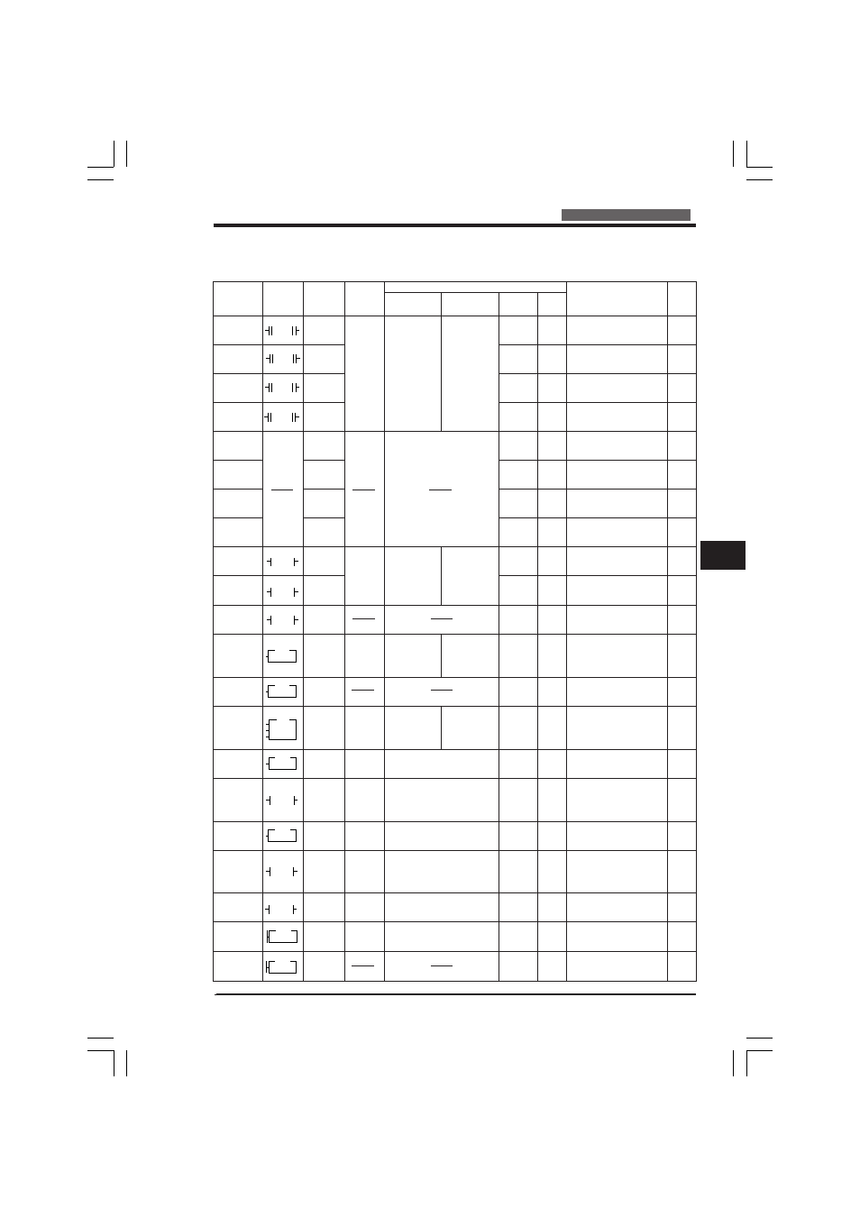
2.2 Instruction List
2.2.2
Application Instructions
KV-10/16/24/40/80
KV-10/16/24/40/80
Instruction Symbol
Mnemonic Operand Operand value
KV-10/16
Operand value
KV-24/40/80
Exec.time
(
µ
s)
Bytes
Function
Page
WAIT ON
WAIT OFF
WAIT UP
EDGE
WAIT DOWN
EDGE
CONNECT
PUSH
READ
POP
STAGE
JUMP
END
STAGE
STEP
STEP END
INTERVAL
TIMER
8-BIT
COUNTER
8-BIT
COUNTER
COMPARA-
TOR
16-BIT
COUNTER
16-BIT
COUNTER
COMPARA-
TOR
SUBROU-
TINE CALL
SUBROU-
TINE ENTRY
SUBROU-
TINE
RETURN
W-ON
nnnn
ON
mmmm
W-OFF
nnnn
OFF
mmmm
W-UE
W-D
CON
[FNC 06]
MPS
MRD
MPP
STG
[FNC 44]
JMP
[FNC 21]
ENDS
[FNC 14]
STP
[FNC 45]
STE
[FNC 43]
ITVL
CTH
CTC
CTH
CTC
CALL
[FNC 03]
SBN
[FNC 38]
RET
[FNC 33]
nnnn:
R,T, or C
No.
R No.
R, T, C
Nos.
DM & R
No.
Clock
source Rs
n:
Comparator
No.
ddddd: #
preset value
Clock
source Rs
n: Compara-
tor No.
ddddd: #
preset value
Subrou-
tine No.
Subrou-
tine No.
nnnn
↑
mmmm
nnnn
↓
mmmm
nnnn
STG
nnnn
JMP
ENDS
STP
nnnn
STE
ITVL
PLS
PAUSE
RES
nnnn
mmmm
DM
nnnn
CTH0
#ddddd
CTCn
nnnn
CTH1
#ddddd
CTCn
nn
CALL
nn
SBN
RET
nnnn:
0000 to 2915
T000 to T063
C000 to C063
CTC0 to CTC3
mmmm:
1000 to 1915
1000 to 1915
0000 to 2915
T000 to T063
C000 to C063
CTC0 to CTC3
DM0000 to
DM0985
1000 to 1912
0004
2100 to 2102
n: 0,1
ddddd: #00000 to #00255
0005
2200 to 2202
n: 2,3
ddddd: #00000 to #65535
00 to 99
00 to 99
nnnn:
0000 to 6915
T000 to T119
C000 to C119
CTC0 to CTC3
mmmm:
1000 to 1915
3000 to 6915
1000 to 1915
3000 to 6915
0000 to 6915
T000 to T119
C000 to C119
CTC0 to CTC3
DM0000 to
DM1985
1000 to 1912
3000 to 6912
11.0 to
13.0
11.0 to
13.0
14.0 to
18.0
14.0 to
18.0
0.4 to
0.6
11.0 to
14.0
8.0 to
10.0
10.0 to
12.0
11.0 to
14.0
10.0 to
13.0
7.0 to
9.0
3.7 to
5.3
0.00
29.0 to
79.0
9.0 to
39.0
3.0 to 4.0
8.0 to
48.0
3.0 to 4.0
8.0 to
10.0
0.00
4.6 to 6.2
5 (7)
5 (7)
5 (7)
5 (7)
301
1 (3)
1 (3)
1 (3)
3 (7)
3 (5)
1 (3)
3 (7)
1 (0)
5 (7)
4 (4)
2 (5)
4 (4)
2 (5)
2 (6)
2 (0)
1 (5)
Turns ON R (2nd operand
[mmmm]) when R, T, or C (1st
operand [nnnn]) turns ON.
When R, T, or C (1st operand
[nnnn]) turns OFF, R (2nd
operand [mmmm]) turns ON.
R (2nd operand [mmmm])
turns ON at rising edge of R, T,
or C (1st operand [nnnn]).
R (2nd operand [mmmm])
turns ON at falling edge of R,
T, or C (1st operand [nnnn]).
Represents series connection
of output instruction together
with another instruction.
Stores input status and
arithmetic flag.
Reads input status and
arithmetic flag stored with
PUSH.
Reads & clears input status
and arithmetic flag stored with
PUSH.
Executes instructions between
STG & JMP when R
(operand) is ON.
Turns current stage OFF and
next stage ON when input is
ON.
Turns current stage OFF when
input is ON.
Executes program between
STP & STE when R (operand)
is ON.
Is used with STEP to make
program step.
Measures pulse-to-pulse
interval & pulse width in
specified mode.
8-bit (0 to255) up-counter for
clock pulses with input
response frequency of 10 kHz.
Hardware-based comparator
between preset & current
values of high speed counter.
This comparator is turned ON
when these values are equal.
16-bit (0 to 65535) up-counter
for clock pulses with input
response frequency of 10 kHz.
Hardware-based comparator
between preset & current
values of high speed counter.
This comparator is turned ON
when these values are equal.
Executes subroutine specified
by operand.
Represents beginning of
subroutine specified by
operand.
Represents end of subroutine.
3-96
3-96
3-98
3-98
3-102
3-103
3-103
3-103
3-106
3-106
3-106
3-114
3-114
3-117
3-277
3-277
3-204
3-204
3-122
3-122
3-122
KVNKA Chap 02_1&2&3P.p65
08.3.11, 11:53 AM
45