KEYENCE Visual KV Series User Manual
Page 376
8.2 Details
3-352
8
Chapter 8 Programming Examples
1 0 1 1 1 0 1 1 1 0 1 1 1 0 1 1
D
15
D
14
D
13
D
12
D
11
D
10
D
9
D
8
D
7
D
6
D
5
D
4
D
3
D
2
D
1
D
0
0 0 0 0 0 0 0 0 1 1 1 1 1 1 1 1
0 0 0 0 0 0 0 0 1 0 1 1 1 0 1 1
0 0 0 0 0 0 0 0 1 0 1 0 1 0 1 0
0 0 0 0 0 0 0 0 0 0 0 1 0 0 0 1
ANDA
EORA
$BBBB
$00FF
$00BB
$00AA
$0011
7000 to 7015
Operand
Internal register
DM0000
Internal register → 2010 is OFF. When the
value of internal register
is 0000, 2010 turns ON.
Judges match between the operand and the data of 7000 to 7015.
#00099
0000
C001
0001
2002
2002
ANDA
$F000
2002
STA
ANDA
LDA
08000
DM0000
LDA
7000
SRA
#12
2002
2002
ORA
STA
TBIN
C001
SLA
#04
$000F
DM0000
Sets C001.
Sends the data of 7012 to 7015 to internal
register.
Shifts the value of internal register to right by
12 bits and writes it into DM0000.
Sends the data of 8000 to 8003 to internal
register.
Shifts the data of internal register to left by 4
bits, ORs the internal register data and the
data of DM0000, and sends the ORed data to
internal register.
Converts the data of internal register to BIN
data and writes it into C001.
2008
2002
LDA
7000
ANDA
$00FF
DM0000
EORA
LDA
$00AA
STA
DM0000
2010 0500
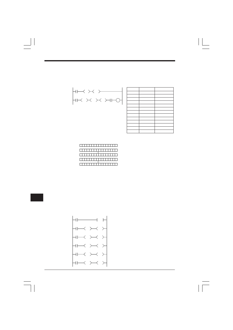
Application of EORA instruction
■ Judgement of matching data
Turns ON 0500 (“OK” output) when the ON/OFF statuses of input relays 7000 to
7007 match the DM0000 setting value.
Ladder diagram
Coding
For easy comprehension, the following data is set temporarily.
When 2010 is ON, the two values match.
When 2010 is OFF, the two values do not match.
➮ Refer to p. 3-164.
Application of SRA/SLA instructions
■ Separate input of BCD
Fetches only 2 digits of the BCD digital switch (7012 to 7015 for the 1st digit, 8000 to
8003 for the 2nd digit) and sets it as the counter value.
Ladder diagram
Line No. Instruction
Operand
0000
LD
2008
0001
LDA
$00AA
0002
CON
0003
STA
DM0000
0004
LD
2002
0005
LDA
7000
0006
CON
0007
ANDA
$00FF
0008
CON
0009
EORA
DM0000
0010
CON
0011
AND
2010
0012
OUT
0500
KVNKA Chap 08.p65
08.3.11, 0:12 PM
352