6 application of the cam switch (cam switch mode), Visual kv series – KEYENCE Visual KV Series User Manual
Page 260
4.5 Special Functions Using High-speed Counters
3-236
Visual KV
Series
4
Chapter 4 High-speed Counters
4.5.6
Application of the Cam Switch (Cam Switch Mode)
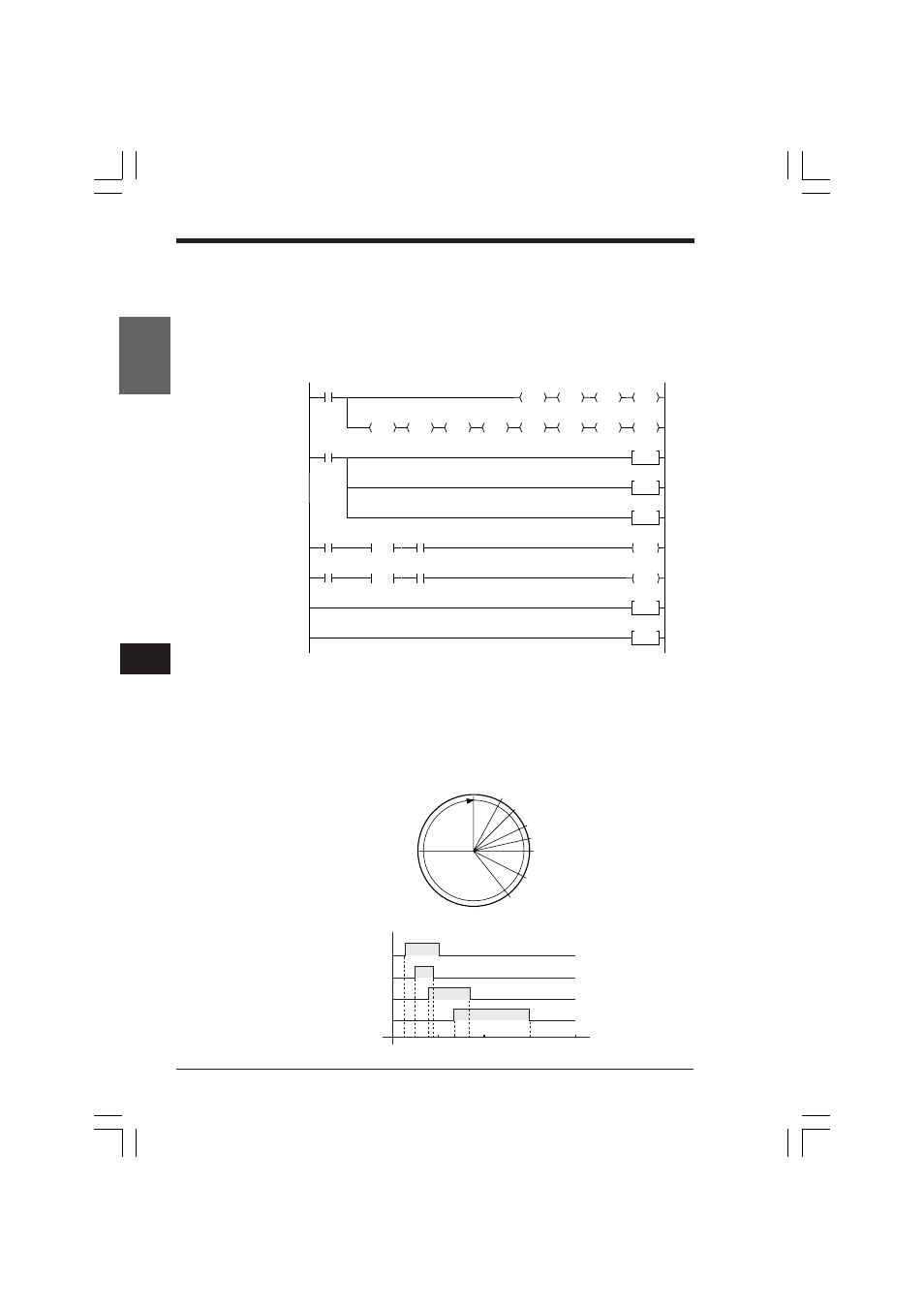
The following ladder program illustrates the basic setting of the cam switch function.
Connect the encoder with a resolution of 360 pulses.
Use output relays 0600 through 0603.
Output relay 0600: Turns ON within the range 30° to 90°
Output relay 0601: Turns ON within the range 45° to 80°
Output relay 0602: Turns ON within the range 70° to 150°
Output relay 0603: Turns ON within the range 120° to 270°
1) Sets "0600", which is the initial number of relays used for the cam switch function, to
DM1400 and sets twice the number of pulses for one encoder rotation (360 x 2 = 720) to
DM1402.
2) Specifies the preset angles at which output relays 0600 through 0603 turn ON/OFF.
3) Sets the input time constant for input relay 0004 to 10 µs.
4) Sets the input time constant for input relay 0006 to 10 µs.
5) Sets the input time constant for input relay 0008 to 10 µs.
6) The cam switch operation starts when input relay 0000 turns ON.
7) The cam switch operation stops when input relay 0001 turns ON.
#00720
LDA
DM1402
STA
#00600
LDA
DM1400
STA
2008
2002
0001
0000
HSP
0004
HSP
0006
HSP
0008
ENDH
END
0001
0002
0005
0007
0003
0004
0008
0006
0009
#02700
DW
DM1413
#01200
DW
DM1412
#01500
DW
DM1411
#00700
DW
DM1410
#00800
DW
DM1409
#00450
DW
DM1408
#00900
DW
DM1407
#00300
DW
DM1406
1000
1001
DIFU
1000
DIFU
1001
2314
SET
2715
RES
1)
2)
5)
3)
6)
4)
7)
3600
(360°)
30° DM1406
45° DM1408
70° DM1410
80° DM1409
90° DM1407
120° DM1412
150° DM1412
90
180
270
360
0
ON
OFF
ON
OFF
ON
OFF
ON
OFF
Timing Diagram
Rotation (°)
1st relay 0600
2nd relay 0601
3rd relay 0602
4th relay 0603
DM1406
DM1407
DM1408
DM1409
DM1410
DM1411
DM1412
DM1413
270°
DM1413
KVNKA Chap 04_2.p65
08.3.11, 0:08 PM
236