Changing the pulse period and width, Visual kv series – KEYENCE Visual KV Series User Manual
Page 262
4.6 Direct Clock Pulse Output
3-238
Visual KV
Series
4
Chapter 4 High-speed Counters
4.6.2
Pulse Output Setting with the High-speed Counter
Comparator
Changing the pulse period and width
By using two high-speed counter comparators, you can change only the pulse width
while keeping the pulse period constant, or change only the pulse period while
keeping the pulse width constant.
The following examples illustrate how the pulse width and period can be selected
with the high-speed counter comparator.
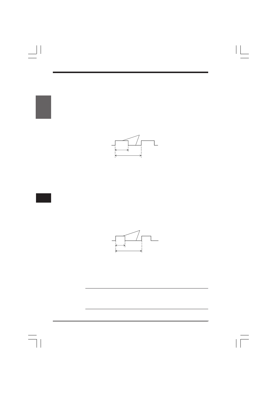
■ ON-OFF ratio of 1:1
Pulse width (µs) = CTC0 preset value x internal clock (µs)
Pulse period (µs) = CTC0 preset value x 2 x internal clock (µs)
Use the following calculation to obtain the pulse period from the frequency:
Pulse period (µs) = 1,000,000/Frequency (Hz)
Example:
To output 10-kHz pulses
Pulse period = 1,000,000 ÷ 10,000 = 100 µs
Preset value for CTC0 = 10 ч 2 ч 1 = 50
■ Variable pulse width
The period and width of the pulse can be changed by changing the preset values of
CTC0 and CTC1.
Pulse width (µs) = CTC1 preset value x internal clock (µs)
Pulse period (µs) = CTC0 preset value x internal clock (µs)
•
Change CTC1 preset value to change the pulse width.
•
Change CTC0 preset value to change the pulse period.
Note: The pulse width determined above is the pulse width produced inside the
Visual KV PLC. In reality, the output pulse width may vary depending on the re-
sponse delay of the output circuit and the load connected to this circuit. Be sure to
determine the pulse width after monitoring the actual output waveform with an
oscilloscope. (Monitor the pulses of variable pulse width.)
OFF
ON
Pulse period
ON/OFF status is set by special utility relays.
Pulse width
OFF
ON
Pulse period
ON/OFF status is set by special utility relays.
Pulse
width
KVNKA Chap 04_2.p65
08.3.11, 0:08 PM
238