2 modifying the input relay time constant, Modification within the cpu – KEYENCE Visual KV Series User Manual
Page 48
1.4 Special Functions
3-24
1
Chapter 1 Programming
1.4.2
Modifying the Input Relay Time Constant
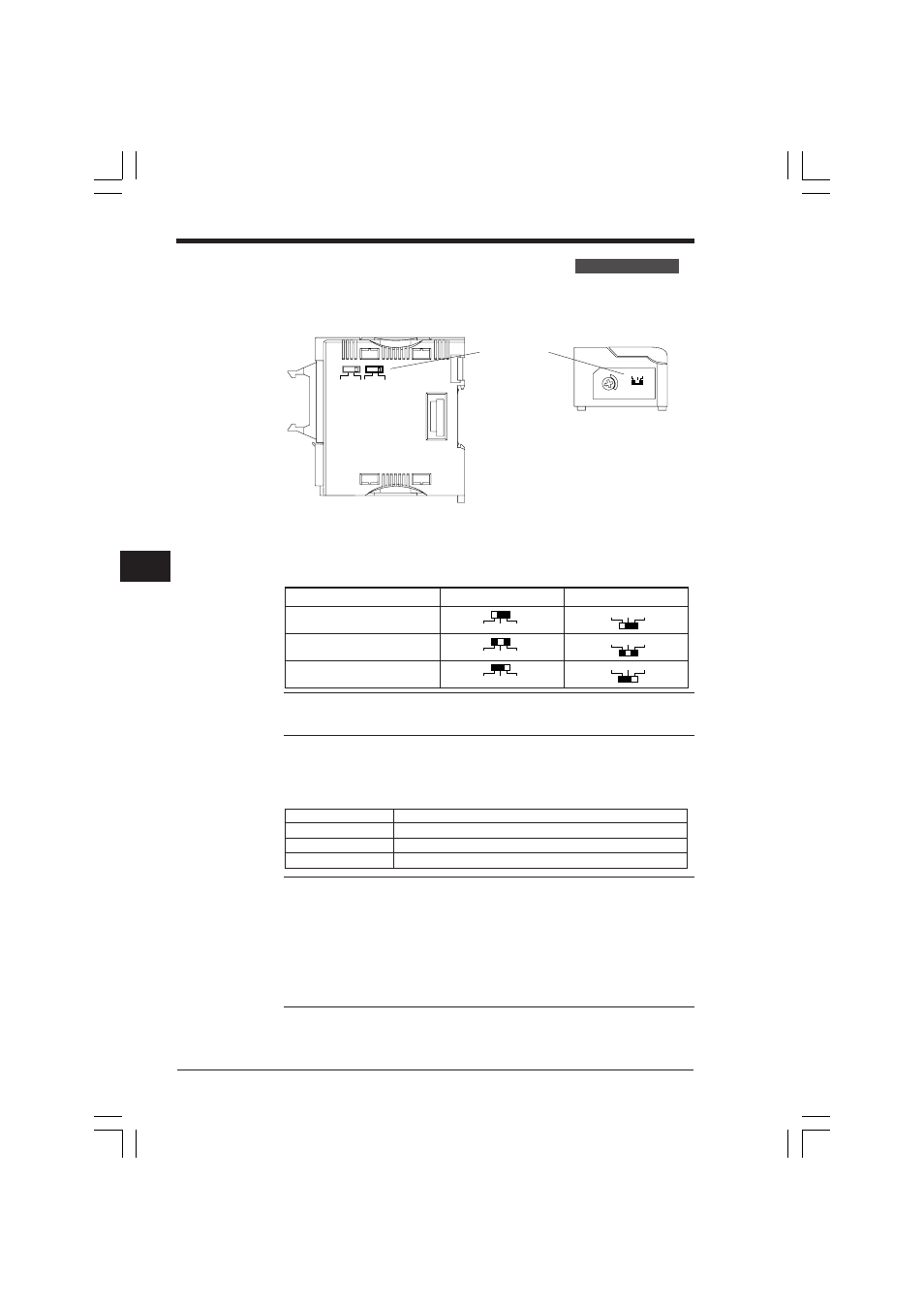
■ Modifying with External Switches
KV-C32X/C16X KV-R16X/R8X
As shown in above figures, an external switch can be used to select the input time
constant only on the KV-C32X/C16X Connector Input Units and KV-R16X/R8X I/O
Terminal Units.
In the following table, white represents the switch position.
Note: Connect a solid-state contact output device when the input time constant is
set to 1 ms for 25 µs. Connection of a contact output device may result in contact
bounce.
Modification within the CPU
The input time constant for KV-300 CPU input relay nos. 0000 to 0009 can be
modified in the program.
Note 1: When using the 30 kHz high-speed counter input, turn ON special utility
relay 2813.
Note 2: When special utility relay 2813 is ON, the input time constant of input relays
0000 to 0009 is set to 10 µs ±20%.
Note 3: The input time constant remains 10 ms ±20% if the HSP instruction is used
when special utility relay 2813 is ON.
Note 4: When the input time constant is set to 10 µs or 25 µs, a solid-state output
device must be connected. Connection of a contact output device may result in
contact bounce.
5V
24V
10 ms
0 ms
1 ms
4
3
2
1
0
1 ms
0 ms
10 ms
Input time constant
selection switch
Input time constant
KV-C32X/C16X
KV-R16X/R8X
25 µs ±20%
1 ms ±20%
10 ms ±20%
0ms 1ms 10ms
0ms 1ms 10ms
0ms 1ms 10ms
0ms 1ms 10ms
0ms 1ms 10ms
0ms 1ms 10ms
Input time constant
Setting
10 µs ±20%
Turn ON special utility relay 2813 (0000 to 0009).
25 µs ±20%
Use the HSP instruction.
10 ms ±20%
Default
KV-300 PLC Only
KVNKA Chap 01P.p65
08.3.11, 11:49 AM
24