Visual kv series – KEYENCE Visual KV Series User Manual
Page 275
4.7 Examples of Direct Clock Pulse Output
3-251
Visual KV
Series
1
4
Chapter 4 High-speed Counters
4.7.4
Application of Direct Clock Pulse Output
(Ramp-up/down control)
The following ramp-up/down control is available by setting four parameters (DM0000
to DM0003)
■ Setting parameters
DM0000: fH [Hz] (Running frequency)
DM0001: fL [Hz] (Start-up frequency)
DM0002: Acceleration rate [Hz/10 ms]
DM0003: No. of pulses for positioning
Note 1: A smaller acceleration rate allows smoother control but extends the accel-
eration time.
Note 2: Be sure to turn OFF input 0007 (phase B input).
■ Operation
In the example on the next page, each parameter is set as follows:
DM0000: 8000 [Hz]
DM0001: 700 [Hz]
DM0002: 400 [Hz/10 ms]
DM0003: 4000 pulses
When start switch 0000 is pressed, ramp-up/down control is performed as shown
below. Control is stopped when the pulse count reaches "4000".
Pressing the start switch restarts the operation. The operation is reversed while
reverse switch 0001 is ON.
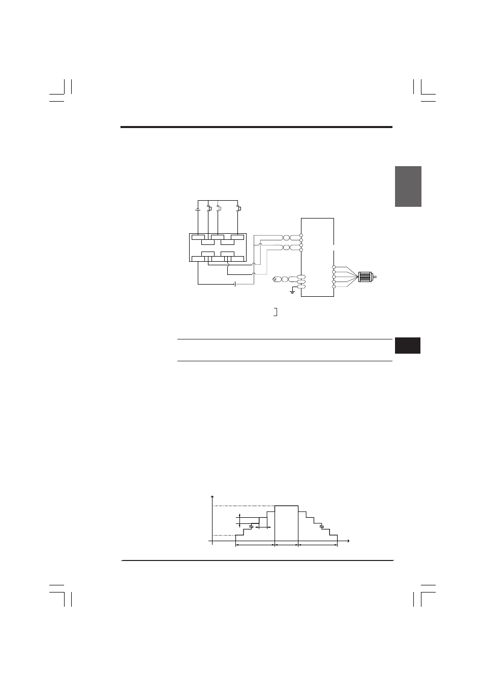
■ Connection example
The above diagram shows a connection example between the KV PLC and a
stepping motor driver.
Refer to the instruction manual for your stepping motor driver for details.
Set the pulse input method of the stepping motor driver to "1-pulse input method".
CW
KV
24 VDC
FG
–
+
–
+
–
+
5 VDC
+
–
CCW
0002
0001
0000
0502
0500
COM
0003
0501
COM
0503
Stepping motor
Start
Reverse
output
Emergency
stop
Stepping motor driver
Twisted-pair cable
(Pulse)
(Rotation
direction)
Specify values in the range from 153 Hz to
50000 Hz. The fH value must be greater
than the fL value.
➞ (fH - fL) / (Acceleration time / 10 ms)
➞ Must be 65534 pulses or less.
L
(DM0001)
H
(DM0000)
10ms
(DM0003)
(DM0002)
0
Frequency (Hz)
Acceleration
rate
(Acceleration
change period)
Total pulses
for positioning
Acceleration
time
Constant
speed time
Time (ms)
Deceleration
time
➞
KVNKA Chap 04_2.p65
08.3.11, 0:08 PM
251