3 example of an extended ladder diagram – KEYENCE Visual KV Series User Manual
Page 55
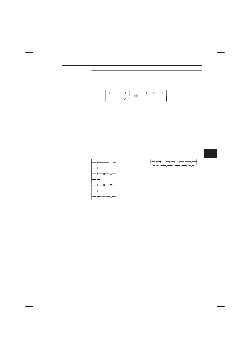
1.5 Extended Ladder Diagrams
3-31
1
1
Chapter 1 Programming
0501
0500
0000
LD 0000
OUT 0500
OUT 0501
LD 0000
OUT 0500
CON
OUT 0501
0501
0500
0000
The CON instruction for connection is added.
(The scan time is not affected.)
At the rising edge of input
0001, 1002 turns ON.
0001
1000
1002
0000
0002
1000
1001
1003
1000
1001
1001
0500
1003
DIFU
1002
DIFU
0500
0000
1000
0001
1000
1001
0002
1001
At the rising edge of input
1003, 1002 turns ON.
If input 0000 is ON, 1000
turns ON.
If 1000 is ON, 1001 turns ON.
When 1001 turns ON, output 0500
turns ON.
Input 0000
turns ON.
Input 0001
turns ON.
Input 0002
turns ON.
Output 0500
turns ON.
Note: When an extended ladder diagram is used, the number of lines in ladder
diagram may be reduced. However, this may not necessarily reduce the number of
mnemonics in the program.
Conventional ladder diagram
Extended ladder diagram
1.5.3
Example of an Extended Ladder Diagram
■ Using W-UE
Only when inputs are given in the order "0000
➞ 0001 ➞ 0002", output 0500 turns
ON.
Conventional ladder diagram
Extended ladder diagram
Because the program can be written in only one line when an extended adder
diagram is used, it is easier to look at and understand compared with a program
written using a conventional ladder diagram.
KVNKA Chap 01P.p65
08.3.11, 11:49 AM
31