KEYENCE Visual KV Series User Manual
Page 202
2.4 Instruction Details
3-178
2
Chapter 2 Instructions
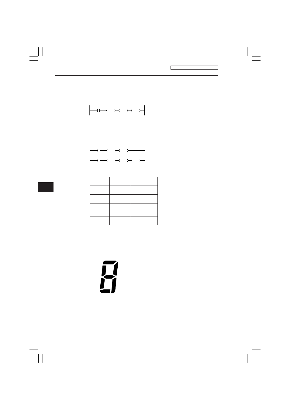
a
d
g
f
b
a : 0600
b : 0601
c : 0607
d : 0603
c : 0604
f : 0605
g : 0606
e
c
■ DMX instruction
Connect sensors 0 to 15 to input relays 0000 through 0015.
Connect output relays 0500 through 0503 to the one-digit data of a BIN indicator.
The sensors which are currently ON are shown by the BIN indicator.
* Assume that several sensors do not turn on simultaneously.
When sensor 8 is ON, the indicator shows "8".
■ Output of error input No. in BCD
Outputs the error sensor No. from input relay 0000 to 0015 to output relays 0500 to
0507 in 2-digit BCD.
Coding
■ Display of 7-segment LED
Displays the current value of counter C007 to the 7-segment LED.
Outputs from 0600 to 0615.
7-segment configuration
2002
0000
LDA
DMX
0500
STA
Line No.
Instruction
Operand
0000
LD
2002
0001
LDA
0000
0002
CON
0003
DMX
0004
LD
2002
0005
TBCD
0006
CON
0007
ANDA
$00FF
0008
CON
0009
STA
0500
0000
LDA
2002
2002
DMX
TBCD
$00FF
ANDA
0500
STA
Converts internal register data to BCD data, executes an
ANDA instruction, and outputs the data to 0500 to 0507.
Converts the most significant bit of 16-bit data (0000 to
0015) to 4-bit BIN data and sends it to internal register.
MPX / @MPX / DMX / @DMX
KVNKA Chap 02_4dP.p65
08.3.11, 0:04 PM
178