Kv -300 – KEYENCE Visual KV Series User Manual
Page 307
6.2 High-speed Counters
KV
-300
KV-10/80
3-283
1
6
Chapter 6 Interrupts, High-speed Counters, Positioning Control
Calculating the pulse cycle and comparator setting value
The KV-300 CPU supports clock pulse output at maximum frequency of 50 kHz.
Obtain the pulse cycle for clock pulse output and comparator setting value from the
following expressions:
•
Pulse cycle
Pulse cycle (µs) = 1000 ÷ Frequency (kHz)
•
For pulse with 1:1 ON/OFF ratio (using one comparator)
CTC setting value = Pulse cycle (µs) ÷ Internal clock (µs) ÷ 2
•
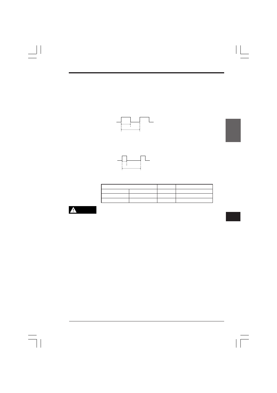
For pulse with variable pulse width (using two comparators)
CTC setting value for pulse width = Pulse width (µs) ÷ Internal clock (µs)
CTC setting value for pulse cycle = Pulse cycle (µs) ÷ Internal clock (µs)
Range of CTC setting based on internal clock
•
When setting 2100 or 2200 for the operand of High-speed counter CTH, set
10 or greater value to CTC. Otherwise, clock pulse is not correctly output.
•
The pulse width varies depending on the influence of the connected load.
Before setting the pulse width, you should measure the actual waveform
using an oscilloscope.
•
When generating clock pulse using CTC0 and CTC1, or CTC2 and CTC3,
do not set the same value to CTC0 and CTC1, or CTC2 and CTC3. If setting
the same value, clock pulse is output at the double clock cycle.
➮ * Refer to page 3-276.
ON
OFF
Pulse
width
Pulse cycle
ON
OFF
Pulse
width
Pulse cycle
CAUTION
Special utility relay (Internal clock)
Cycle
* CTC setting range
2100
2200
1.0 µs
10 to 65535
2101
2201
10.0 µs
1 to 65535
2102
2202
100.0 µs
1 to 65535
KVNKA Chap 06.p65
08.3.11, 0:10 PM
283