Kv -300 – KEYENCE Visual KV Series User Manual
Page 315
6.2 High-speed Counters
KV
-300
KV-10/80
3-291
1
6
Chapter 6 Interrupts, High-speed Counters, Positioning Control
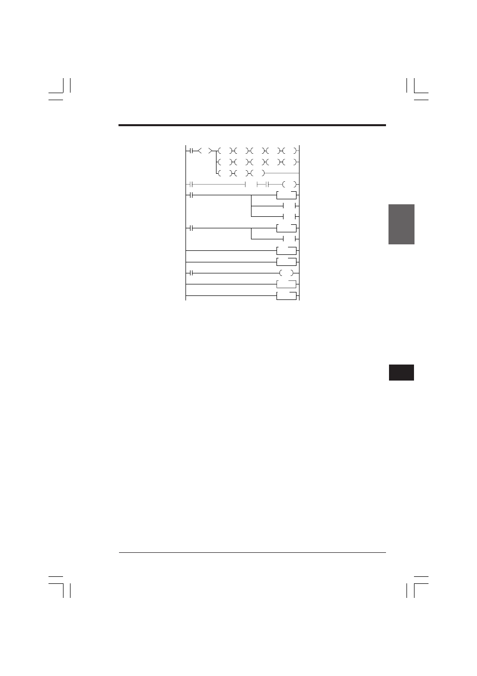
Programming example
2008
SET
2103
2104
2105
2106
2002
0001
0002
0003
2101
RES
SET
SET
RES
CTH0
CTC0
#00050
0004
0005
RES
2108
2109
2110
2111
CTH0
SET
RES
RES
RES
2107
CTC1
#00020
END
INT
CTC2
2002
SET
2105
RET1
ENDH
SET
2203
2813
SET
2105
RES
CTH1
RES
EI
0000
1000
DIFU
1000
0006
0007
2002
0500
CTH1
CTC2
#10000
0008
0009
0010
0011
0012
0013
0014
•
Sets pulse output to 0500 using special utility relays 2104 to 2107 and 2108 to
2111.
The example on the left sets special utility relays to enable direct output to 0500
(2104: OFF), and turn 0500 output ON at CTC0 (2106: ON) and OFF at CTC1
(2109: ON).
•
Turns ON special utility relay 2103 to clear CTH0 using CTC0. This allows output
with correct clock pulse width starting from the 1st pulse.
•
Enables interrupt using the EI instruction.
Stops clock pulse using interrupt program (INT CTC2) when the current value of
High-speed counter CTH1 reaches the setting value of high-speed counter
comparator CTC2 (when 10000 pulses are output).
•
Turns ON special utility relay 2203 to clear CTH1 using CTC2. This allows
program to operate repeatedly at the specified pulse count (10000 pulses).
•
Always turns ON 2813 when counting pulses using high-speed counter CTH1.
•
Input relay which enables CTH0 remains ON during clock pulse output.
•
Input relay which enables CTH1 remains ON during clock pulse counting.
•
Specifies internal clock (2101) for clock input of high-speed counter CTH0.
Specifies 0500 for clock input of high-speed counter CTH1. Then, CTH0 is used
for clock pulse output and CTH1 is used for clock pulse counting.
•
Sets the clock pulse count using the setting value of high-speed counter com-
parator CTC2.
•
Turns ON input relay 0000 to start clock pulse output.
To restart clock pulse output after once stopped, turns ON input relay 0000
again.
KVNKA Chap 06.p65
08.3.11, 0:10 PM
291