Setting and application of parameters, Kv -300 – KEYENCE Visual KV Series User Manual
Page 321
6.3 Positioning Control
KV
-300
KV-10/80
3-297
1
6
Chapter 6 Interrupts, High-speed Counters, Positioning Control
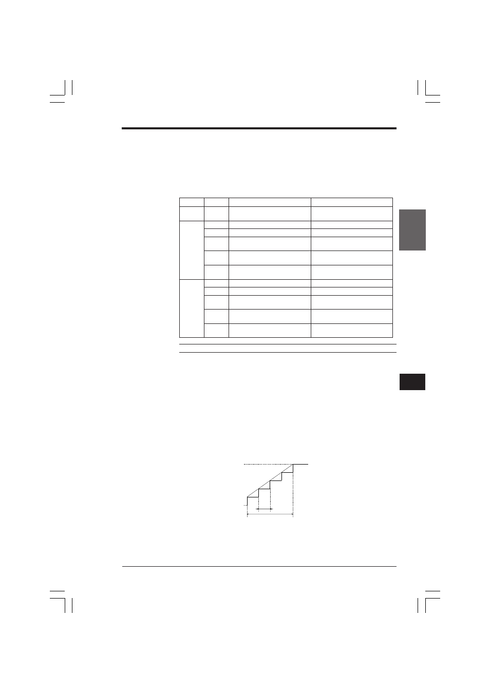
Run
Start
Acceleration/ deceleration time
∆t
Setting and application of parameters
This section describes how to set and apply parameters for positioning control.
Setting parameters
Set the parameters to the assigned data memory addresses. To operate the
positioning control function, the special utility relays must be set.
➮ Refer to page 3-299.
The following table shows the parameters and assigned DM Nos.
Note: Refer to the following expression to determine the output pulse count.
Output pulse count < (65535 x pulse change cycle [ms]) ÷ (1000 x run frequency
[Hz])
■ Pulse change cycle (∆t)
The pulse change cycle is the cycle in which the output clock pulse frequency is
changed for acceleration or deceleration. The pulse change cycle is obtained from
one of the following expressions, whichever produces the smaller solution. However,
when the start pulse is less than 500 Hz, the pulse change cycle becomes 14 ms or
more.
Pulse change cycle (∆t) [ms] = (acceleration time [ms] + 199) ÷ 200 x 4
or
Pulse change cycle (∆t) [ms] = 1000 ÷ (run frequency [Hz] ÷ 1000)
DMNo.
Parameter
Allowable setting range
DM9407
Set value error code
Code 11 to 17 or FFFF (-1)
is entered when error occurs
X-axis
DM9408
0500 Start frequency (Hz)
153 to 50000
(0500)
DM9409
0500 Run frequency (Hz)
153 to 50000
DM9410
0500 Acceleration/deceleration
0 to 4096
time (ms)
DM9411
0500 Output pulse count
0 to 65535
(high-order 16 bits)
DM9412
0500 Output pulse count
0 to 65535
(low-order 16 bits)
Y-axis
DM9413
0501 Start frequency (Hz)
153 to 50000
(0501)
DM9414
0501 Run frequency (Hz)
153 to 50000
DM9415
0501 Acceleration/deceleration
0 to 4096
time (ms)
DM9416
0501 Output pulse count
0 to 65535
(high-order 16 bits)
DM9417
0501 Output pulse count
0 to 65535
(low-order 16 bits)
KVNKA Chap 06.p65
08.3.11, 0:10 PM
297