3 frequency counter function, Visual kv series – KEYENCE Visual KV Series User Manual
Page 255
4.5 Special Functions Using High-speed Counters
3-231
Visual KV
Series
1
4
Chapter 4 High-speed Counters
4.5.3
Frequency Counter Function
High-speed counter CTH0 is used. Write the interval (ms) of frequency measure-
ment into data memory DM1404 and turn ON special utility relay 2305. The mea-
surement result (Hz) is written into DM1405.
Input relay 0004 is for pulse input (single-phase input). Input relay 0006 (phase B
input) is ignored.
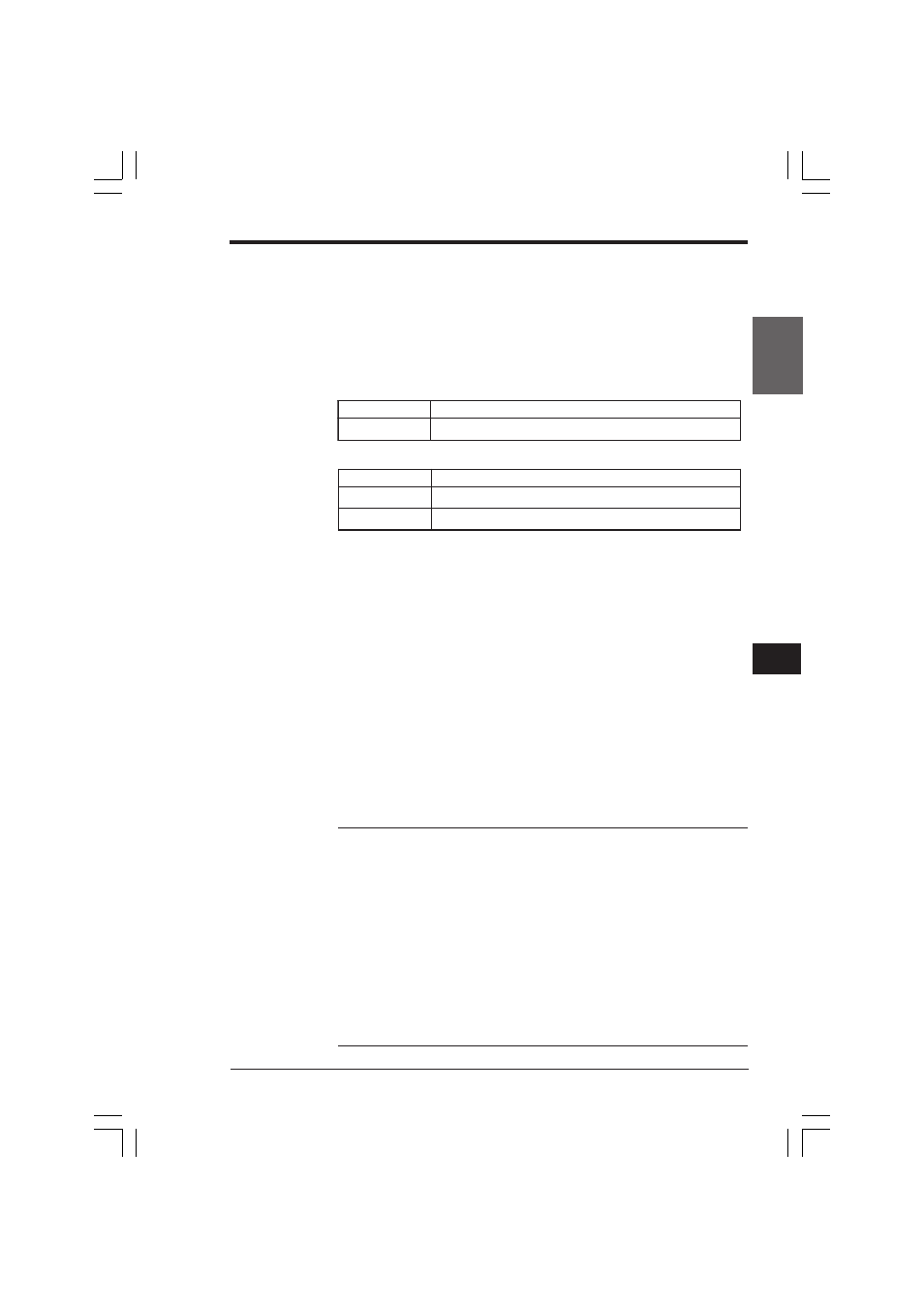
■ Devices used with the frequency counter
Special utility relays
Data memory
■ Operation flow
1. Set the high-speed counter with external input. Use the END instruction and
measure how much time has elapsed since the last measurement in units of 10
µs. After each scan, pulses are counted within the time specified with the data
memory. The frequency is calculated from the count value and written into data
memory.
2. When the time specified with DM1404 elapses from the last measurement, the
current value of CTH0 is fetched and divided by the elapsed time (Unit: 10 µs).
The frequency is obtained with the following calculation.
Frequency (Hz) = (100,000 x Pulse count)/Elapsed time (Unit: 10
µ
s)
3. The calculation result (Hz) is written into DM1405.
■ Setting method
1. Specify the counting period for the frequency counter (the interval of frequency
measurement [Unit: ms]) in data memory DM1404.
2. The preset value must be greater than the scan time. When a value smaller than
the scan time is specified, the frequency is measured each scan time.
Note 1: To use the frequency counter function, set the input time constant to 10 µs
with the HSP instruction or the special utility relay. (A maximum frequency of 30 kHz
can be measured.).
Note 2: The counting start/stop or measurement result is updated after each scan.
Therefore, the counting period includes some scan time errors for the time specified
with DM1404. Set the counting period so that overflow does not occur at CTH.
Note 3: Specify the counting period so that the number of pulse inputs in one period
is between 2 and 65535, inclusive.
Note 4: Measurement may fail when the pulse period is 5000 ms or more.
Note 5: The frequency counter cannot be used when CTH0 is used in the ladder
program.
Note 6: Special utility relays concerning CTH0, CTC0/1, and the cam switch cannot
be used.
Note 7: CTH0 and the cam switch function cannot be used when the frequency
counter is used.
.
o
N
y
a
l
e
R
n
o
i
t
p
i
r
c
s
e
D
5
0
3
2
o
N
:
F
F
O
,
s
e
Y
:
N
O
.
r
e
t
n
u
o
c
y
c
n
e
u
q
e
r
f
e
s
U
.
o
N
M
D
n
o
i
t
p
i
r
c
s
e
D
4
0
4
1
M
D
]
0
0
0
1
o
t
1
[
r
e
t
n
u
o
c
y
c
n
e
u
q
e
r
f
f
o
)
s
m
(
e
l
c
y
c
t
n
e
m
e
r
u
s
a
e
M
5
0
4
1
M
D
r
e
t
n
u
o
c
y
c
n
e
u
q
e
r
f
f
o
)
z
H
(
t
n
u
o
c
y
c
n
e
u
q
e
r
f
f
o
t
l
u
s
e
R
KVNKA Chap 04_2.p65
08.3.11, 0:08 PM
231