12 relay nos. and functions – KEYENCE Visual KV Series User Manual
Page 46
1.3 Device Configuration
3-22
1
Chapter 1 Programming
1.3.12 Relay Nos. and Functions
Assignment of Relay Nos.
The components of a relay no. are shown below.
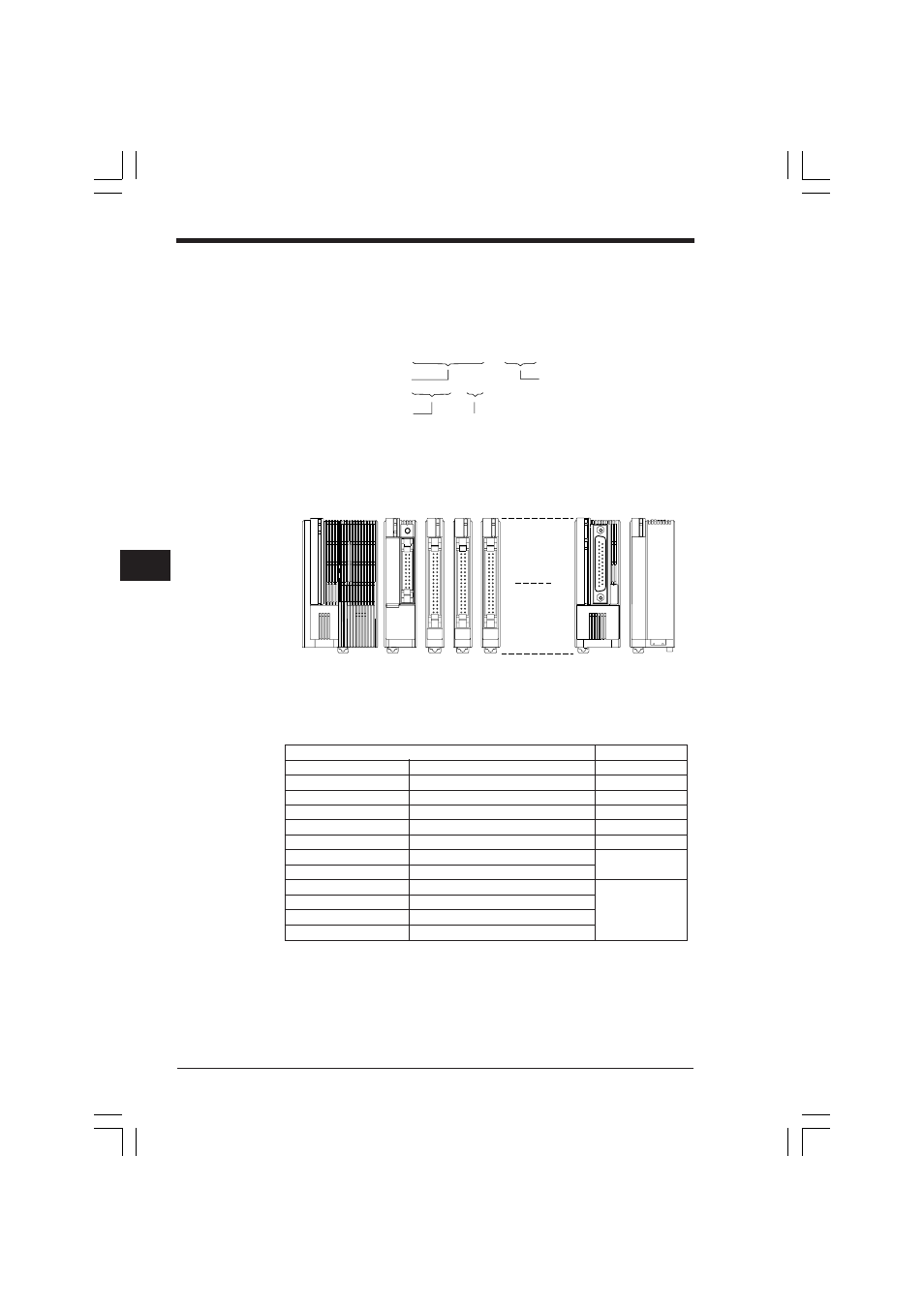
■ Unit Nos.
Unit nos. are assigned to units within the KV-300 system, with the unit connected to
the right of the KV-300 CPU (see the figure below) assigned as no. 7. The CPU is
assigned as unit no. 0.
■ Address Nos.
Address nos. are assigned to the input units, output units, and I/O terminal units.
The following table shows the assignment of address nos. to units.
*
The KV-R1A I/O Distribution Unit accommodates 5 input units and 5 output units.
Addresses are set with address switches.
0 7 5 1 5
Address No.
Channel No.
Relay No. (00 to 15)
Module No. (07 to 17)
Input (0 to 4)
Output (5 to 9)
Power supply unit
CPU
0
7
8
9
16
17
Unit
Address No.
KV-300 CPU
CPU
0, 5
KV-C16X
16-input unit
0
KV-C32X
32-input unit
0. 1
KV-B16R
16-output unit
5
KV-B16S
16-output unit
5
KV-C32T
32-output unit
5, 6
KV-R8X
8-input terminal unit
0 to 4 *
KV-R16X
16-input terminal unit
KV-R8R
8-output terminal unit
5 to 9 *
KV-R16R
16-output terminal unit
KV-R8T
8-output terminal unit
KV-R16T
16-output terminal unit
KVNKA Chap 01P.p65
08.3.11, 11:49 AM
22