Kv -300 – KEYENCE Visual KV Series User Manual
Page 304
6.2 High-speed Counters
KV
-300
KV-10/80
3-280
6
Chapter 6 Interrupts, High-speed Counters, Positioning Control
Pulse period and width
Period and width of the pulse is determined by the period of the internal clock (CTH)
used and the preset value of the comparator (CTC).
When two counter comparators are used, only the pulse width can be changed while
a constant period is maintained.
The following examples illustrate how pulse width and period can be selected:
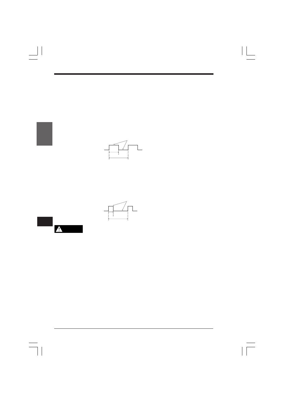
■ ON/OFF ratio of 1:1
Pulse width (ms) = CTC0 preset value x internal clock (ms)
Pulse period (ms) = CTC0 preset value x 2 x internal clock (ms)
•
ON/OFF ratio of pulse is 1:1.
•
Change CTC0 preset value to change the pulse width and period.
■ Variable pulse width
ON/OFF status is set by special utility relays.
Pulse width (ms) = CTC1 preset value x internal clock (ms)
Pulse period (ms) = CTC0 preset value x internal clock (ms)
•
Change CTC1 preset value to change the pulse width.
•
Change CTC0 preset value to change the pulse period.
The pulse width determined as above is used to pulses generated from the
KV-300 CPU.
Pulses are output through the output circuit. The pulse width varies depend-
ing on the response delay from the output circuit and influence of the con-
nected load. Before setting the pulse width, you should measure the actual
waveform using an oscilloscope. (Use pulses with variable pulse width.)
•
To obtain the pulse cycle from frequency, use the following expression:
Pulse cycle (µs) = 1000 ÷ Frequency (kHz)
ON
OFF
Pulse
width
Pulse period
ON/OFF status is set special utility relays
ON
OFF
Pulse period
ON/ OFF status is set by special utility relays
Pulse
width
CAUTION
KVNKA Chap 06.p65
08.3.11, 0:10 PM
280