5 extended ladder diagrams, 1 features of extended ladder diagrams – KEYENCE Visual KV Series User Manual
Page 53
1.5 Extended Ladder Diagrams
3-29
1
1
Chapter 1 Programming
1.5
Extended Ladder Diagrams
This section describes KEYENCE’s unique extended ladder diagram.
1.5.1
Features of Extended Ladder Diagrams
The extended ladder diagram is a programming method developed to reduce
problems related to design, testing, operation, and maintenance of programs.
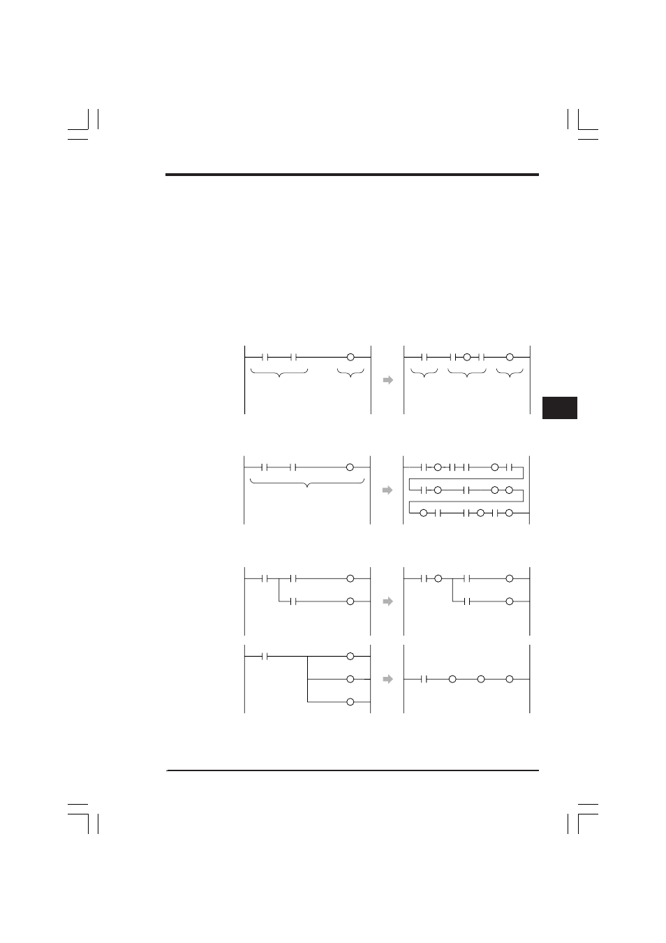
In a conventional ladder diagram, output instructions can be written only on the right
side of a ladder diagram. On the other hand, in an extended ladder diagram, output
instructions can be written anywhere except on the left. As the result, the programs
shown below can be written.
Mixture of input and output circuits
Conventional ladder diagram
Extended ladder diagram
Connection of two or more instructions on one line
Conventional ladder diagram
Extended ladder diagram
Branch from output coil
Conventional ladder diagram
Extended ladder diagram
Only input circuits
can be written.
Only output
circuits can
be written.
Only input
circuits can
be
assembled.
Both input
circuits and
output circuits
can be
assembled.
Only output
circuits can
be
assembled.
Instructions can be written only from the
left end to the right end on one line.
Many instructions can be connected.
There is only a single line, so the ladder
diagram is easier to understand.
Branches can be made only from input
contacts.
Three lines are required.
Branches can also be made from output
coils.
KVNKA Chap 01P.p65
08.3.11, 11:49 AM
29