1 outline of positioning control, 1 ramp-up/down control, Visual kv series – KEYENCE Visual KV Series User Manual
Page 278
5.1 Outline of Positioning Control
3-254
Visual KV
Series
5
Chapter 5 Positioning Control
5.1
Outline of Positioning Control
This section describes the outline of positioning control.
5.1.1
Ramp-up/down Control
The Visual KV Series can directly output clock pulses not affected by the scan time
to output relay 0502.
If the frequency, the number of output pulses, and the acceleration time of the clock
pulses have been preliminarily set to data memories, the Visual KV Series automati-
cally performs ramp-up/down control.
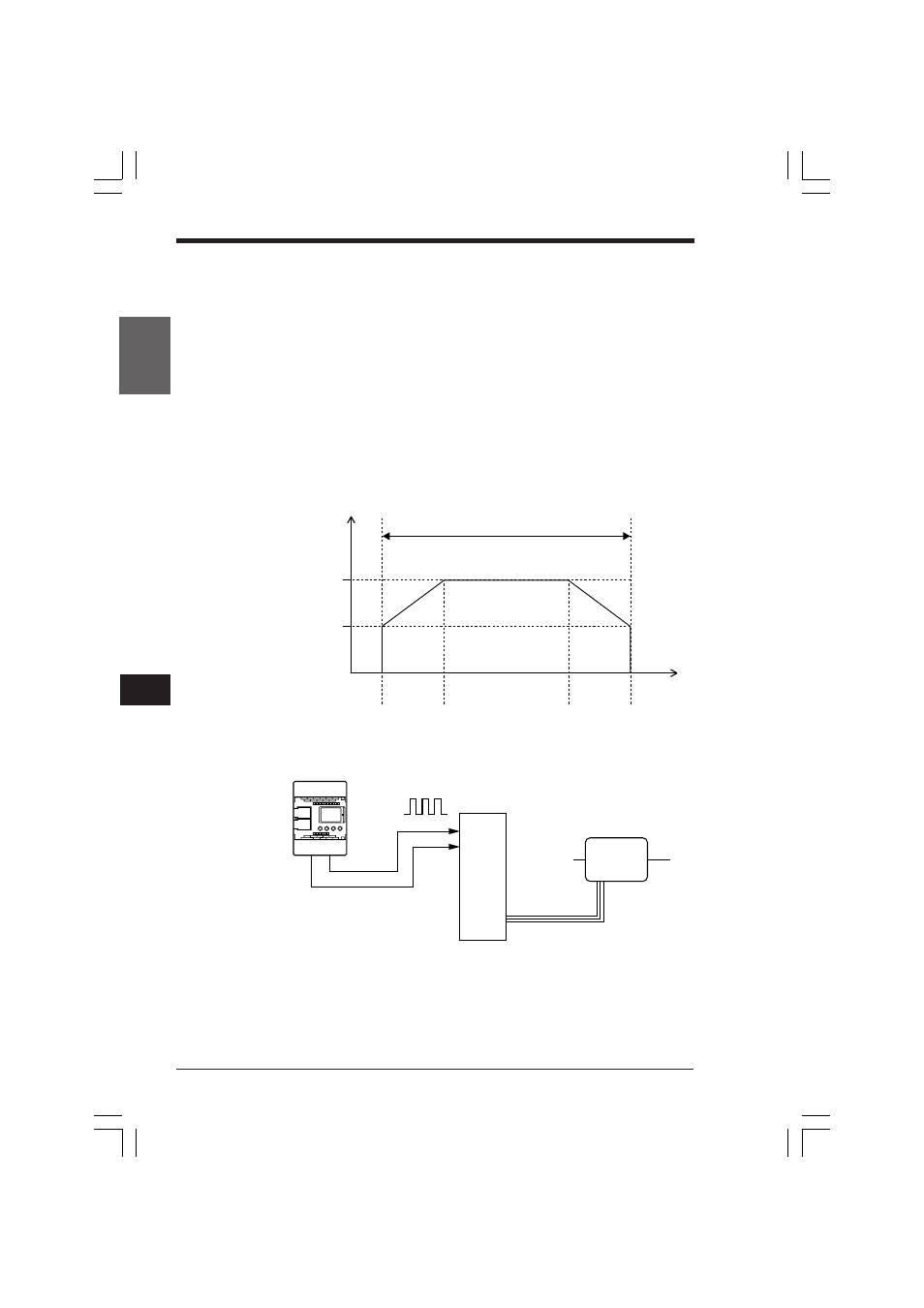
The ramp-up/down control output function offers ramp-up/down timing charts of the
startup frequency, operating frequency, acceleration time, and deceleration time as
shown below.
The output frequency can be set within the range of 200 to 50,000 Hz.
By using the ramp-up/down control output function, ramp-up/down control of step-
ping motors and AC servo motors (pulse input types) is possible.
Frequency (Hz)
Number of output
pulses (pulses)
DM1485 and DM1484
Operating
frequency
DM1481
Upper digit
Lower digit
Startup
frequency
DM1480
Acceleration
time DM1482
Deceleration
time DM1482
Time (ms)
NEW KV
Lo: CW
Hi: CCW
0502
0503
Clock pulse
Rotation direction
Motor driver
Stepping motor
Servo motor
KVNKA Chap 05.p65
08.3.11, 0:09 PM
254