Visual kv series – KEYENCE Visual KV Series User Manual
Page 225
3.4 Applications of Interrupt Programs
3-201
Visual KV
Series
1
3
Chapter 3 Interrupts
3.4.4
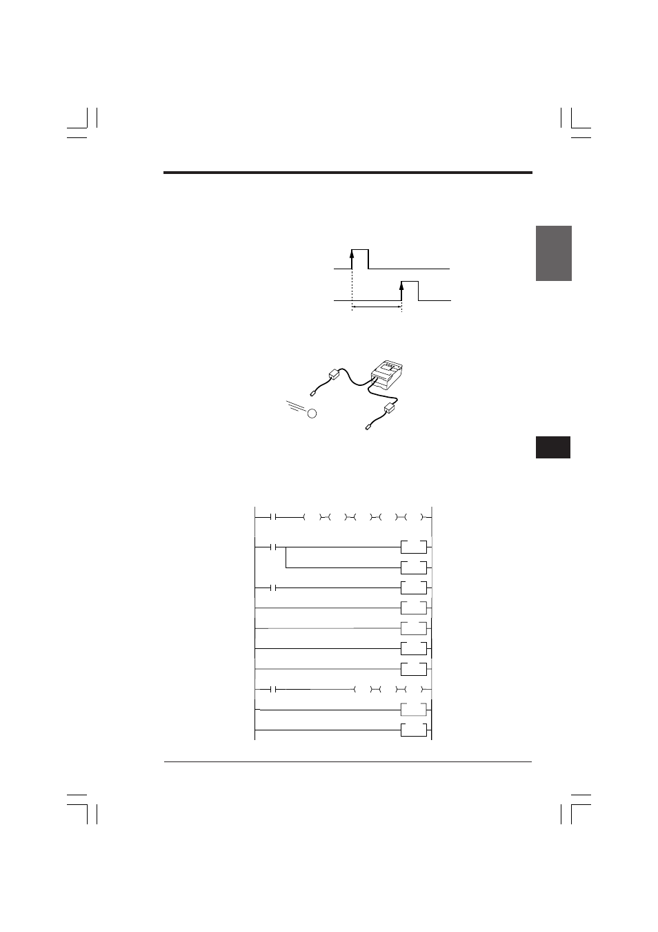
Measuring the Period in which a Target Passes between
Two Points
■ Outline
Measures the period in which two input relays turn ON.
Example: Measurement of tact time
■ Ladder diagram
•
Measures the time from when input relay 0002 turns ON until input relay 0003
turn ON.
•
The measured value is written to data memory DM0000 (Unit: µs).
0001
0002
0003
0004
0005
0006
0007
0008
0009
0010
0011
2008
EI
2002
HSP
0002
HSP
0003
2002
CTH1
2200
2411
RES
2412
RES
2413
RES
2410
RES
END
INT
0002
RETI
RETI
ENDH
INT
0003
DM0000
STA
DM1932
SUB
DM1934
LDA
2002
• When power is turned on, an
EI instruction enables inter-
rupts. Sets the interrupt polarity
of inputs 0002 and 0003 to the
rising edge.
• Sets the input time constant of
inputs 0002 and 0003 to 10 µs.
• CTH1 counts the pulses using
a 1-µs internal clock.
• When INT2 is executed, the
current value of CTH1 is
automatically transferred to
DM1932 and DM1933 (Input
capture).
• When INT3 is executed, the
current value of CTH1 is
automatically transferred to
DM1934 and DM1935 (Input
capture).
Subtracts the input capture
value of INT2 from that of INT3
to obtain the time it takes for
the target to pass between two
points and then writes it to
DM0000.
OFF
ON
OFF
ON
Sensor 1 input 0002
Sensor 2 input 0003
Passing time (µs)
Sensor 1
Sensor 2
Visual KV
KVNKA Chap 03.p65
08.3.11, 0:05 PM
201