KEYENCE Visual KV Series User Manual
Page 59
Visual KV Series
3-35
1
2
Chapter 2 Instructions
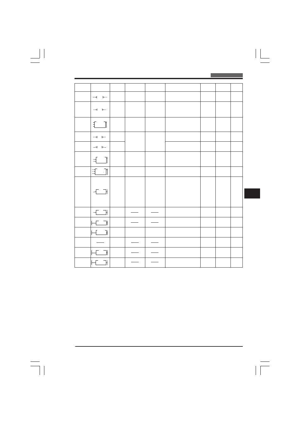
2.1 Instruction List
•
Number of bytes represents the memory capacity required for each instruction.
•
Number in ( ) represents the memory capacity required for object code of each
instruction.
•
*1 34 + 0.25 + n x 0.25 (n: No. of shift steps)
•
All operand values are shown in normal notation. The corresponding relay num-
bers in X-Y-M notation are shown below:
Normal notation
X-Y-M notation
0000 to 0415
X000 to X04F
0500 to 0915
Y050 to Y09F
1000 to 6915
M1000 to M6915
7000 to 17915
X700 to X174F or Y750 to Y179F
Instruction
Symbol
Mnemonic
Operand
Operand value
Function
Exec.time
(
µ
s)
Bytes
Page
1-ms
TIMER
TMS
(FUN51)
COUNTER
C
# preset value,
C No., counter
input R
UP-DOWN
COUNTER
UDC
(FUN52)
C No.,
# preset value
#00000 to
#65535
000 to 249
0000 to 17915
000 to 249
#00000 to
#65535
12.0 to 17.8
12.0 to 17.8
13.0 to 24.0
2 (7)
4 (7)
2 (10)
16-bit on-delay T that
counts down in 1-ms
decrements.
Sets 16-bit up-counter.
Sets a 16-bit up-down
counter.
000 to 249
#0000 to #65535
3-72
3-76
3-69
DIFFEREN-
TIATE UP
DIFU
(FUN10)
R No.
DIFFEREN-
TIATE
DOWN
DIFD
(FUN09)
KEEP
KEEP
(FUN22)
R No.
SHIFT
SFT
(FUN39)
nnnn: 1st R
No. mmmm:
Last R No.
HIGH
SPEED
HSP
(FUN18)
R No.
MASTER
CONTROL
MC
(FUN24)
MASTER
CONTROL
RESET
MCR
(FUN25)
MEMORY
SWITCH
MEMSW
(FUN26)
$ constant
NOP
NOP
(FUN30)
END
END
END HI
ENDH
1000 to 1915
3000 to 9915
0500 to 1915
2009
2100 to 17915
1000 to 1915
3000 to 9915
(KV-10)
0000 to 0005
(KV-16)
0000 to 0009
(KV-24)
0000 to 0015
(KV-40)
0000 to 0107
$ 0000 to
$ FFFF
11.2 to 13.2
10.0 to 12.8
8.2 to 19.8
(*)
3.8 to 9.4
0.2
0.2
––
––
––
––
3 (10)
3 (10)
3 (11)
5 (15)
3 (8)
1 (4)
1 (0)
3 (0)
1 (0)
1 (1)
1 (0)
Turns ON R for 1 scan
time at rising edge of
input.
Turns ON R for 1 scan
time at falling edge of
input.
Turns ON R and holds this
status when SET input is ON.
Turns OFF R when RESET
input is ON.
Sets shift register.
Reduces input relay time
constant to 10 µs for
higher input response.
Selects ON/OFF status of
R coils, Ts, or Cs.
Represents end of MC.
Sets memory switches.
Performs no operation.
Indicates end of each
routine of program.
Indicates end of entire
program.
3-78
3-78
3-80
3-82
3-86
3-89
3-89
T No.,
# preset value
3-94
3-94
3-94
#ddddd
T
xxx
T
S
#ddddd
nnnn
Cxxx
UDC xxx
#ddddd
UP
DW
RES
nnnn
DIFU
nnnn
DIFD
KEEP
SET
RES
nnnn
SFT
nnnn
mmmm
D
CLK
RES
HSP
nnnn
MC
MCR
MEMSW
$xxxx
END
ENDH
3-92
KVNKA Chap 02_1&2&3P.p65
08.3.11, 11:52 AM
35