Kv -300 – KEYENCE Visual KV Series User Manual
Page 310
6.2 High-speed Counters
KV
-300
KV-10/80
3-286
6
Chapter 6 Interrupts, High-speed Counters, Positioning Control
Values set to the internal clock and CTC2
After the internal clock is determined, the CTC2 setting value is calculated from the
following expression.
CTC2 setting value = Pulse cycle (µs) ÷ Internal clock (µs) ÷ 2
Assign 1 ms to pulse cycle and 10 µs (2201: special utility relay) to internal clock
and calculate the CTC2 setting value.
The calculated result is "50".
CTC2 values calculated based on other internal clocks are listed below for your
reference.
➮ * Refer to page 3-276.
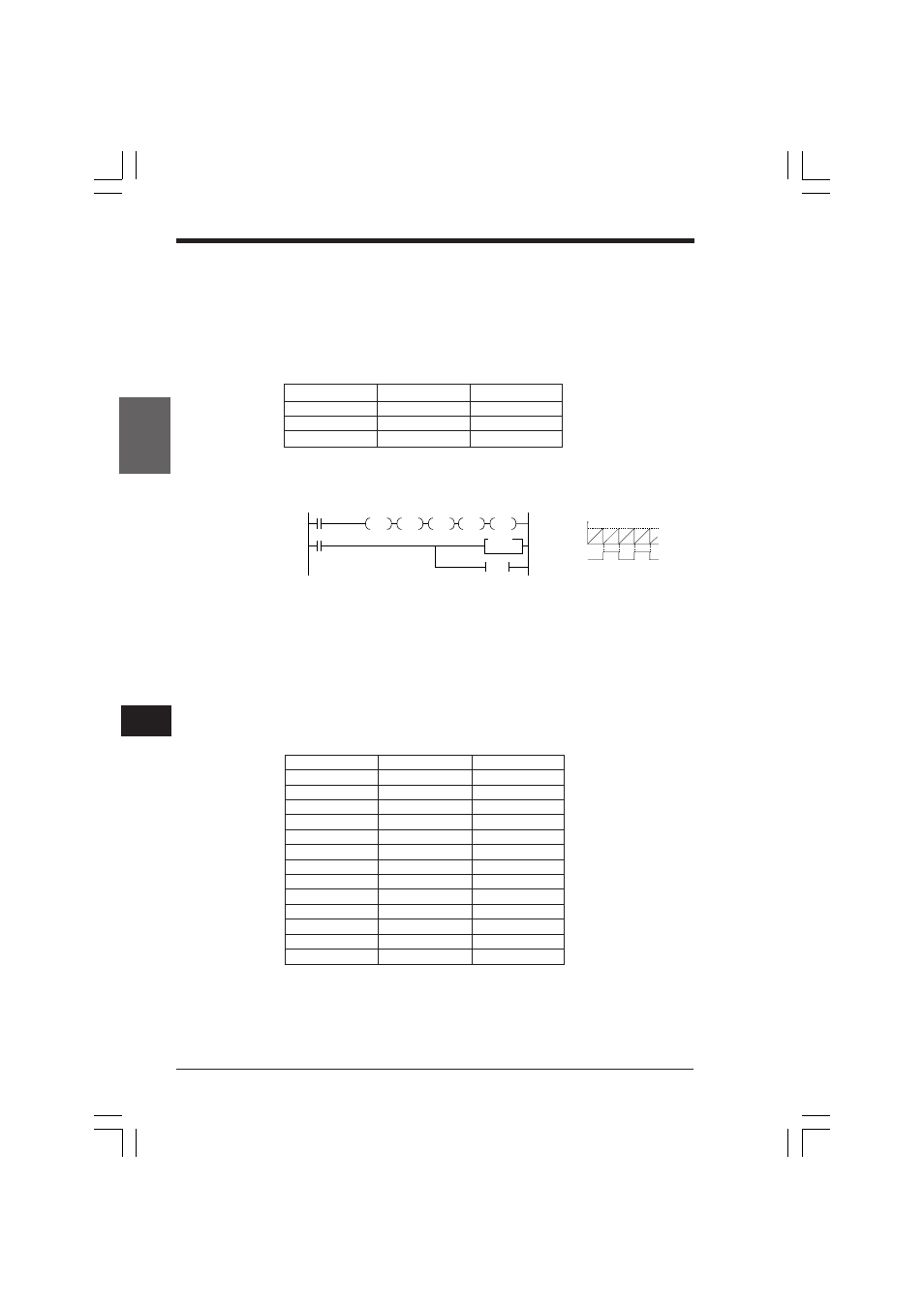
Programming example
•
The status of output 0501 is set by turning ON one of the relays 2204 to 2207 at
the beginning of the program. In Example, output of direct clock pulses to 0501 is
enabled, and the status of output 0501 is inverted each time CTH1 = CTC2.
•
Turns ON special utility relay 2203 and specifies to clear CTH1 using CTC2. The
program repeats clearing the CTH1 current value with the value set to CTC2.
•
Resetting the current value of CTH1 at the beginning of the program allows direct
clock pulses of specified width to be output starting from the 1st pulse.
•
Input relay which enables CTH1 remains ON during clock pulse output.
Coding
Special utility relay
Internal clock*
CTC0 value
2200
1.0 µs
500
2201
10.0 µs
50
2202
100.0 µs
5
2008
SET
2203
2204
2205
2207
2002
0001
0002
0003
CTH1
2201
SET
RES
SET
RES
CTH1
CTC2
#00050
CTH1 value
ON
OFF
CTC2
Line No.
Instruction
Operand
0000
LD
2008
0001
SET
2203
0002
CON
0003
SET
2204
0004
CON
0005
RES
2205
0006
CON
0007
SET
2207
0008
CON
0009
RES
CTH1
0010
LD
2002
0011
CTH
1 2201
0012
CTC
2 #00050
KVNKA Chap 06.p65
08.3.11, 0:10 PM
286