1 connection example, 2 tips, Visual kv series – KEYENCE Visual KV Series User Manual
Page 282
5.3 Examples of Using the Positioning Control Function
Visual KV
Series
5
Chapter 5 Positioning Control
3-258
5.3
Examples of Using the Positioning
Control Function
This section describes examples of connecting a stepping motor driver and perform-
ing ramp-up/down control using the positioning control function of the Visual KV
Series.
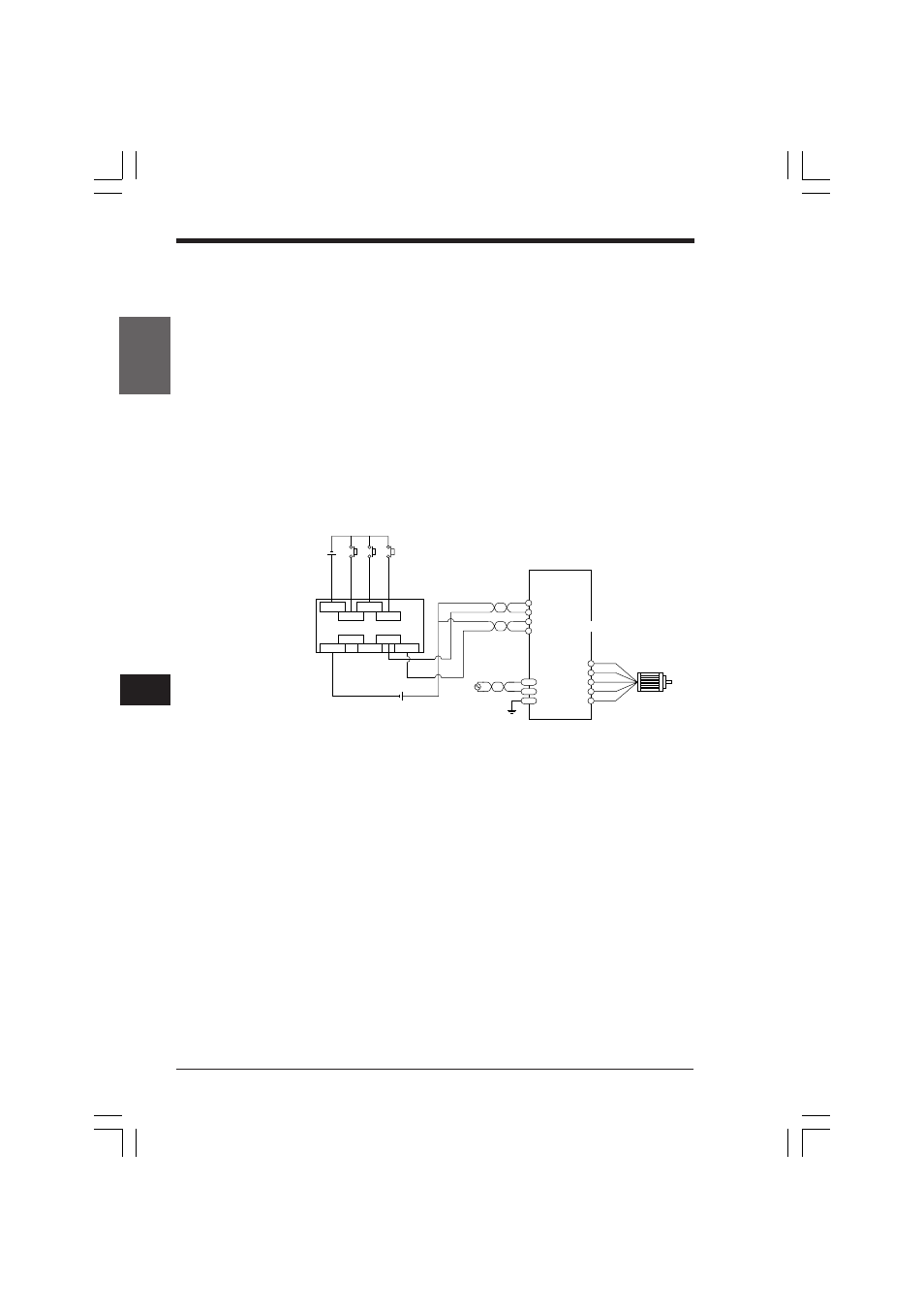
5.3.1
Connection Example
Connect the Visual KV Series and stepping motor driver as shown below.
This example is only for reference. For details, refer to the instruction manual for the
stepping motor driver.
Set the pulse input type of the stepping motor driver to "1 pulse input type".
•
When using a 24 VDC power supply, be sure to use the outputs with current limiting
resistors (R500, R501, and R502) or use the normal outputs with external current limiting
resistors.
5.3.2
Tips
When using a servo motor, also refer to the connection example above. However,
I/O control dedicated to a servo motor such as servo ON is also required.
CW
Visual KV
24 VDC
FG
–
+
–
+
+
–
5 VDC*
+
–
CCW
0 0 0 2
0 0 0 1
0 0 0 0
R 0 5 0 2
C O M
C O M
R 0 5 0 3
Emergency stop
Stop
Start
Stepping motor driver
Twisted pair cable
(pulse)
(rotation
direction)
Stepping motor
KVNKA Chap 05.p65
08.3.11, 0:09 PM
258