KEYENCE Visual KV Series User Manual
Page 351
8.2 Details
3-327
1
8
Chapter 8 Programming Examples
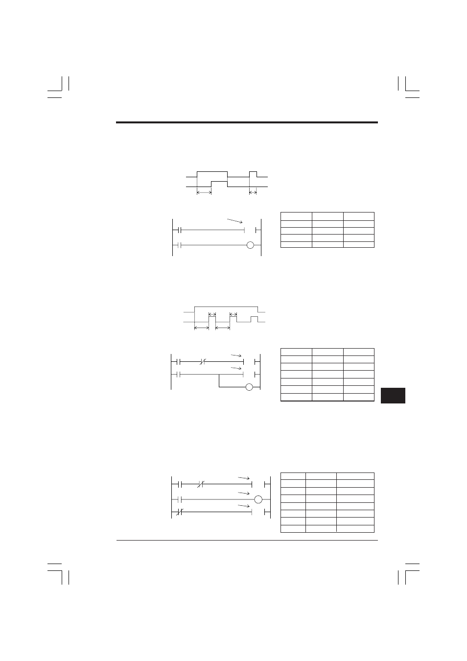
■ On-delay circuit
Output relay 0500 turns ON in a specified time after input relay 0000 turns ON.
When input relay 0000 turns OFF, output relay 0500 also turns OFF.
Timing diagram
Ladder diagram
Coding
■ Flicker circuit
Output relay 0500 turns ON and OFF repeatedly while input relay 0000 is ON.
Timing diagram
Ladder diagram
Coding
■ Accumulator timer (Remains ON in case of power failure)
Counts special utility relay 2006 (1-s clock pulse) for 3600 s at C001 and inputs the
count value to C002. Accumulates the count for 10000 hours and retains the current
count value even when power failure occurs or power is OFF.
Input relay 0000
Reset relay 0001
(Resolution is 1 s at 2006.)
Ladder diagram
Coding
0500
0000
2s
1s
0000
#00020
T000
0500
T000
2-s timer
0500
0000
2s
1s
1s
2s
0000
#00020
T000
T000
2-s timer
0500
#00010
T001
T001
1-s timer
Line No.
Instruction
Operand
0000
LD
0000
0001
TMR
000 #00020
0002
LD
T000
0003
OUT
0500
Line No.
Instruction
Operand
0000
LD
0000
0001
ANB
T001
0002
TMR
000 #00020
0003
LD
T000
0004
TMR
001 #00010
0005
OUT
0500
0000
#03600
C001
C001
3600-s counter
C001
1-s pulse
0001
#10000
C002
10000-s counter
1000
1000
2006
Line No. Instruction
Operand
0000
LD
0000
0001
ANB
C001
0002
C
001 #03600 2006
0003
LD
C001
0004
OUT
1000
0005
LDB
0001
0006
C
002 #10000 1000
KVNKA Chap 08.p65
08.3.11, 0:12 PM
327