Regenerative power supply modules – Lenze 9400 Manual User Manual
Page 283
Regenerative power supply modules
Device description
7
283
EDS94SPP101-7.1
Standard device
Design
Pos.
Description
VR module
MXI1
Expansion slot 1, e.g. for communication
;
MXI2
Expansion slot 2, e.g. for communication
;
MMI
Storage module slot
;
MSI
Reserved
X1
System bus (CAN), under the cover
;
X2
24 V supply and statebus
;
X3
Analog inputs and analog outputs
2/2
X4
Digital outputs
4
X5
Digital inputs
8
X6
Diagnostics
;
X7
Reserved (resolver)
X8
Control signals for mains filter (encoder)
;
Lower cover
;
Retractable nameplate
;
Upper cover
;
Prominent warning label close to the device!
;
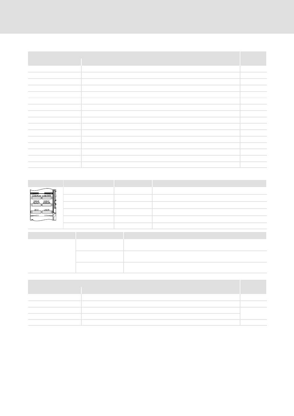
The LED display enables fast indication of several operating states.
LED
Labelling
Colour
Description
CAN-RUN
green
CAN bus ok
CAN-ERR
red
CAN bus error
DRIVE READY
green
Standard device is ready for operation
DRIVE ERROR
red
Error in the standard device or application-induced
24 V
green
24 V supply voltage ok
SSP94LED01
USER
yellow
Message parameterised by the application
Pos.
Symbol
Description
Long discharge time: All power terminals carry hazardous voltages for at
least 3 minutes after mains disconnection!
High discharge current: Fixed installation and PE connection to EN 61800-5-1
required!
Electrostatic sensitive devices: Before working on the device, personnel must
ensure that they are free of electrostatic charge!
Installation backplane
Design
Pos.
Description
VR module
X111
Mains supply via mains filter/DC-bus voltage
;
X112
Mains supply and mains power recovery via mains filter/external brake resistor
;
X109
DC busbar +
;
X110
DC busbar -
EMC shield clamp
;