Power supply modules, Arrangement of the devices, Arrange the devices in a row from left to right – Lenze 9400 Manual User Manual
Page 240
Power supply modules
Mechanical installation
Devices in the range 100 ... 245 A (48 ... 119 kW)
6
240
EDS94SPP101 EN 7.1
Arrangement of the devices
L1
L2
L3
M
3~
M
3~
M
3~
M
3~
E94AZxPxxxx
E94AZxPxxxx
E94APNExxxx
E94AZEX100
E94AZPxxxxx
E94AZPxxxxx
E94AZPxxxxx
E94AZPxxxxx
...
...
+UG
-UG
+UG
-UG
+UG
-UG
0
1
+
(E94AZPPxxxx)
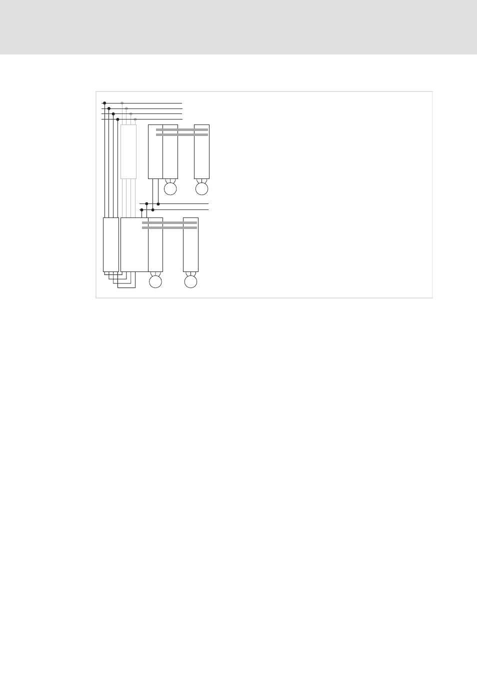
SSP94FF003
Fig. 6-4
Arrangement concept
Standard mounting: side mounting
Mounting variant: top mounting
E94AZxPxxxx
Filter
E94APNExxxx
9400 DC power supply module
(up to 36 A/18 kW with E94AZPPxxxx installation backplane)
E94AZEX100
DC input module
E94AZPxxxxx
Installation backplane for 9400 axis module
A DC-bus connection has to be planned and dimensioned taking the technical data into
account.
How to arrange the devices via the DC busbars for operation in the DC-bus connection:
ƒ
Arrange the devices in a row from left to right.
ƒ
Install the supplying device on the left:
– DC power supply module (in a first row),
– DC input module (in the following rows).
ƒ
Install the multi drive axis controllers to the right from the highest to the lowest
power (recommendation).
ƒ
For increasing the braking power also single drive axis controllers can be integrated.
For this purpose these axis controllers have to be equipped with the optional busbar
mounting set (E94AZJAxxx).