GW Instek GSP-830 User Manual User Manual
Page 15
GETTING
STARTED
15
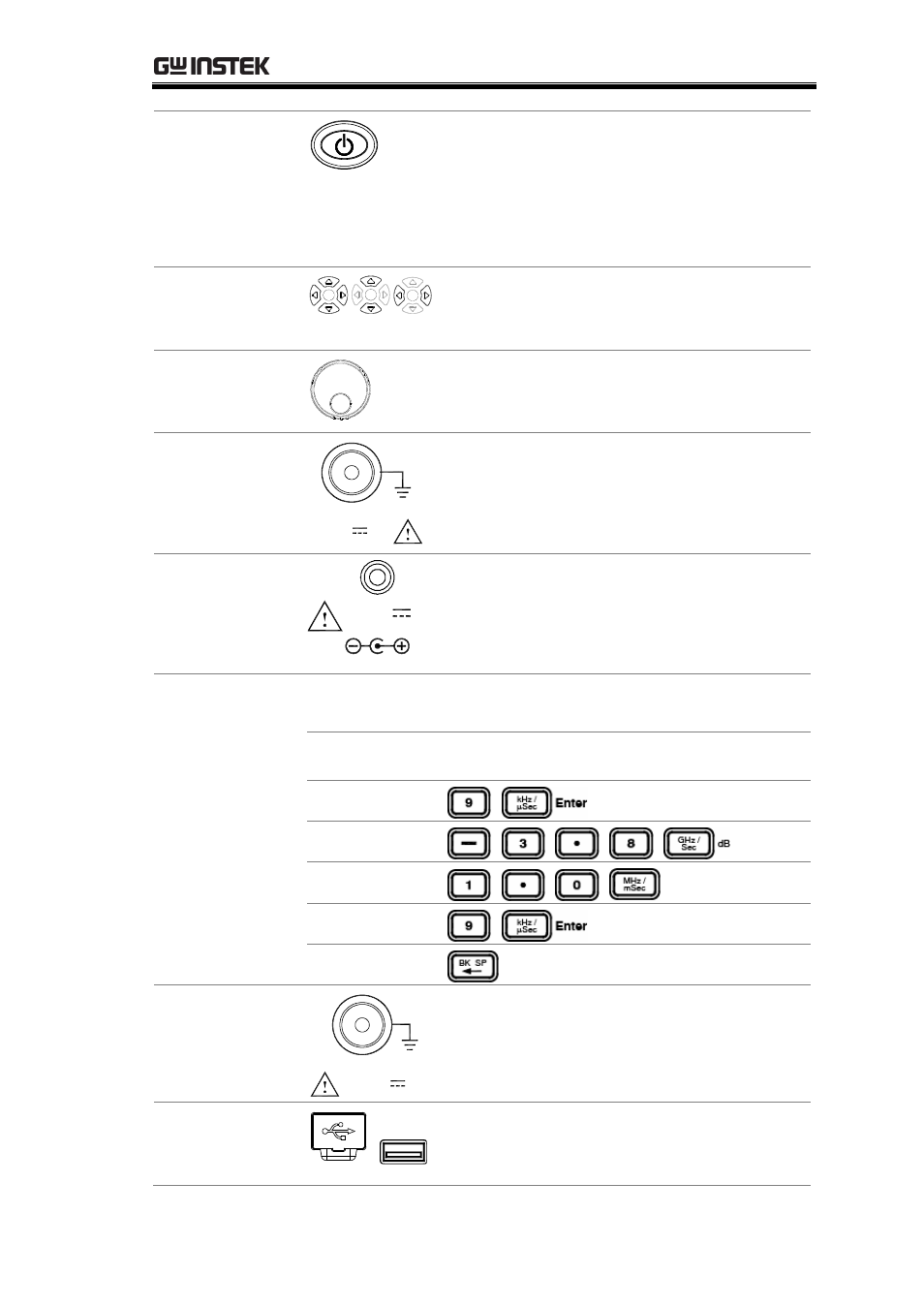
Power Key
Power key selects the power state between
the standby mode (Red LED on) and
power on mode (Green LED on). To turn
on/off the main power, use the power
switch on the rear panel. See page20 for
the power up sequence.
Arrow Keys
Arrow keys select parameters in various
occasions; Up/Right for increasing,
Down/Left for decreasing.
Scroll Knob
Scroll knob sets or selects parameters in
various occasions. In many cases, it works
in tandem with the Arrow keys.
Input Terminal
RF INPUT 50
Ω
+30dBm MAX
MAX
DC ±25V
Input terminal accepts RF input signals.
•
Maximum +30dBm
•
Input impedance 50Ω
Pre-Amplifier
Power Supply
Terminal
100mA MAX.
DC 9V
OUTPUT
Pre-amplifier power supply terminal
provides power for the optional GAP-801
or GAP-802 pre-amplifier. For details, see
page56.
Numerical keys set various parameters. In many cases, they
work in tandem with the Arrow keys and Scroll knob.
Numerical Keys
Unit Keys
Enter Key
BK SP key
Example Key
sequence
9kHz
−3.8dB
1.0mS
9 + Enter
Correction
Optional TG
Output Terminal
TG OUTPUT 50
Ω
MAX
DC ±25V
Outputs the optional Tracking Generator
signal. Reversed power should not exceed
+30dBm. For details, see page142.
USB Host
Connector
Via the USB port (typeA male), display
images may be saved to or recalled from
USB flash drives For details, see page113.