Pin descriptions, Port a (pa7..pa0), Port b (pb7..pb0) – Rainbow Electronics ATmega3290P_V User Manual
Page 6: Port c (pc7..pc0), Port d (pd7..pd0)
6
ATmega329/3290/649/6490
2552H–AVR–11/06
Comparison between
ATmega329,
ATmega3290,
ATmega649 and
ATmega6490
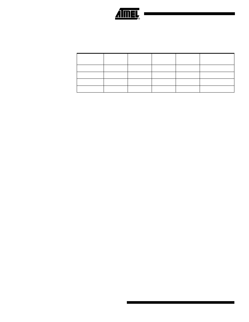
The ATmega329, ATmega3290, ATmega649, and ATmega6490 differs only in memory
sizes, pin count and pinout. Table 1 on page 6 summarizes the different configurations
for the four devices.
Pin Descriptions
The following section describes the I/O-pin special functions.
V
CC
Digital supply voltage.
GND
Ground.
Port A (PA7..PA0)
Port A is an 8-bit bi-directional I/O port with internal pull-up resistors (selected for each
bit). The Port A output buffers have symmetrical drive characteristics with both high sink
and source capability. As inputs, Port A pins that are externally pulled low will source
current if the pull-up resistors are activated. The Port A pins are tri-stated when a reset
condition becomes active, even if the clock is not running.
P o r t A a l s o s e r v e s t h e f u n c t i o n s o f v a r i o u s s p e c i a l f e a t u r e s o f t h e
ATmega329/3290/649/6490 as listed on page 67.
Port B (PB7..PB0)
Port B is an 8-bit bi-directional I/O port with internal pull-up resistors (selected for each
bit). The Port B output buffers have symmetrical drive characteristics with both high sink
and source capability. As inputs, Port B pins that are externally pulled low will source
current if the pull-up resistors are activated. The Port B pins are tri-stated when a reset
condition becomes active, even if the clock is not running.
Port B has better driving capabilities than the other ports.
P o r t B a l s o s e r v e s t h e f u n c t i o n s o f v a r i o u s s p e c i a l f e a t u r e s o f t h e
ATmega329/3290/649/6490 as listed on page 68.
Port C (PC7..PC0)
Port C is an 8-bit bi-directional I/O port with internal pull-up resistors (selected for each
bit). The Port C output buffers have symmetrical drive characteristics with both high sink
and source capability. As inputs, Port C pins that are externally pulled low will source
current if the pull-up resistors are activated. The Port C pins are tri-stated when a reset
condition becomes active, even if the clock is not running.
Port C also serves the functions of special features of the ATmega329/3290/649/6490
as listed on page 71.
Port D (PD7..PD0)
Port D is an 8-bit bi-directional I/O port with internal pull-up resistors (selected for each
bit). The Port D output buffers have symmetrical drive characteristics with both high sink
and source capability. As inputs, Port D pins that are externally pulled low will source
current if the pull-up resistors are activated. The Port D pins are tri-stated when a reset
condition becomes active, even if the clock is not running.
Table 1. Configuration Summary
Device
Flash
EEPROM
RAM
LCD
Segments
General Purpose
I/O Pins
ATmega329
32K bytes
1K bytes
2K bytes
4 x 25
54
ATmega3290
32K bytes
1K bytes
2K bytes
4 x 40
69
ATmega649
64K bytes
2K bytes
4K bytes
4 x 25
54
ATmega6490
64K bytes
2K bytes
4K bytes
4 x 40
69