Osccal - oscillator calibration register – Rainbow Electronics ATmega3290P_V User Manual
Page 29
29
ATmega329/3290/649/6490
2552H–AVR–11/06
Notes:
1. The device is shipped with this option selected.
2. The frequency ranges are preliminary values. Actual values are TBD.
3. If 8 MHz frequency exceeds the specification of the device (depends on V
CC
), the
CKDIV8 Fuse can be programmed in order to divide the internal frequency by 8.
When this Oscillator is selected, start-up times are determined by the SUT Fuses as
shown in Table 10 on page 29.
Note:
1. The device is shipped with this option selected
.
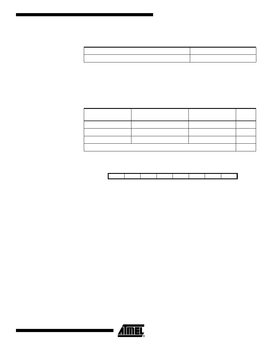
OSCCAL – Oscillator
Calibration Register
• Bits 7:0 – CAL7:0: Oscillator Calibration Value
The Oscillator Calibration Register is used to trim the Calibrated Internal RC Oscillator
to remove process variations from the oscillator frequency. A pre-programmed calibra-
tion value is automatically written to this register during chip reset, giving the Factory
calibrated frequency as specified in Table 143 on page 319. The application software
can write this register to change the oscillator frequency. The oscillator can be calibrated
to frequencies as specified in Table 143 on page 319. Calibration outside that range is
not guaranteed.
Note that this oscillator is used to time EEPROM and Flash write accesses, and these
write times will be affected accordingly. If the EEPROM or Flash are written, do not cali-
brate to more than 8.8 MHz. Otherwise, the EEPROM or Flash write may fail.
The CAL7 bit determines the range of operation for the oscillator. Setting this bit to 0
gives the lowest frequency range, setting this bit to 1 gives the highest frequency range.
The two frequency ranges are overlapping, in other words a setting of OSCCAL = 0x7F
gives a higher frequency than OSCCAL = 0x80.
The CAL6..0 bits are used to tune the frequency within the selected range. A setting of
0x00 gives the lowest frequency in that range, and a setting of 0x7F gives the highest
frequency in the range.
Table 9. Internal Calibrated RC Oscillator Operating Modes
(1)(3)
Frequency Range
(2)
(MHz)
CKSEL3..0
7.3 - 8.1
0010
Table 10. Start-up times for the internal calibrated RC Oscillator clock selection
Power Conditions
Start-up Time from Power-
down and Power-save
Additional Delay from
Reset (V
CC
= 5.0V)
SUT1..0
BOD enabled
6 CK
14CK
00
Fast rising power
6 CK
14CK + 4.1 ms
01
Slowly rising power
6 CK
14CK + 65 ms
10
Reserved
11
Bit
7
6
5
4
3
2
1
0
CAL7
CAL6
CAL5
CAL4
CAL3
CAL2
CAL1
CAL0
OSCCAL
Read/Write
R/W
R/W
R/W
R/W
R/W
R/W
R/W
R/W
Initial Value
Device Specific Calibration Value