Rainbow Electronics ATmega3290P_V User Manual
Page 207
207
ATmega329/3290/649/6490
2552H–AVR–11/06
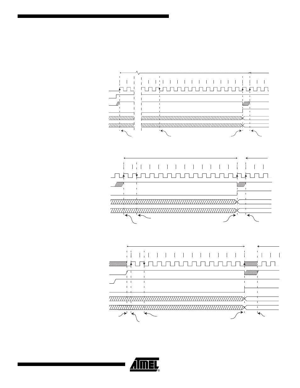
In Free Running mode, a new conversion will be started immediately after the conver-
sion completes, while ADSC remains high. For a summary of conversion times, see
Table 93.
Figure 87. ADC Timing Diagram, First Conversion (Single Conversion Mode)
Figure 88. ADC Timing Diagram, Single Conversion
Figure 89. ADC Timing Diagram, Auto Triggered Conversion
Sign and MSB of Result
LSB of Result
ADC Clock
ADSC
Sample & Hold
ADIF
ADCH
ADCL
Cycle Number
ADEN
1
2
12
13
14
15
16
17
18
19
20
21
22
23
24
25
1
2
First Conversion
Next
Conversion
3
MUX and REFS
Update
MUX and REFS
Update
Conversion
Complete
1
2
3
4
5
6
7
8
9
10
11
12
13
Sign and MSB of Result
LSB of Result
ADC Clock
ADSC
ADIF
ADCH
ADCL
Cycle Number
1
2
One Conversion
Next Conversion
3
Sample & Hold
MUX and REFS
Update
Conversion
Complete
MUX and REFS
Update
1
2
3
4
5
6
7
8
9
10
11
12
13
Sign and MSB of Result
LSB of Result
ADC Clock
Trigger
Source
ADIF
ADCH
ADCL
Cycle Number
1
2
One Conversion
Next Conversion
Conversion
Complete
Prescaler
Reset
ADATE
Prescaler
Reset
Sample &
Hold
MUX and REFS
Update