Rainbow Electronics ATmega3290P_V User Manual
Page 154
154
ATmega329/339/649/659
2552H–AVR–11/06
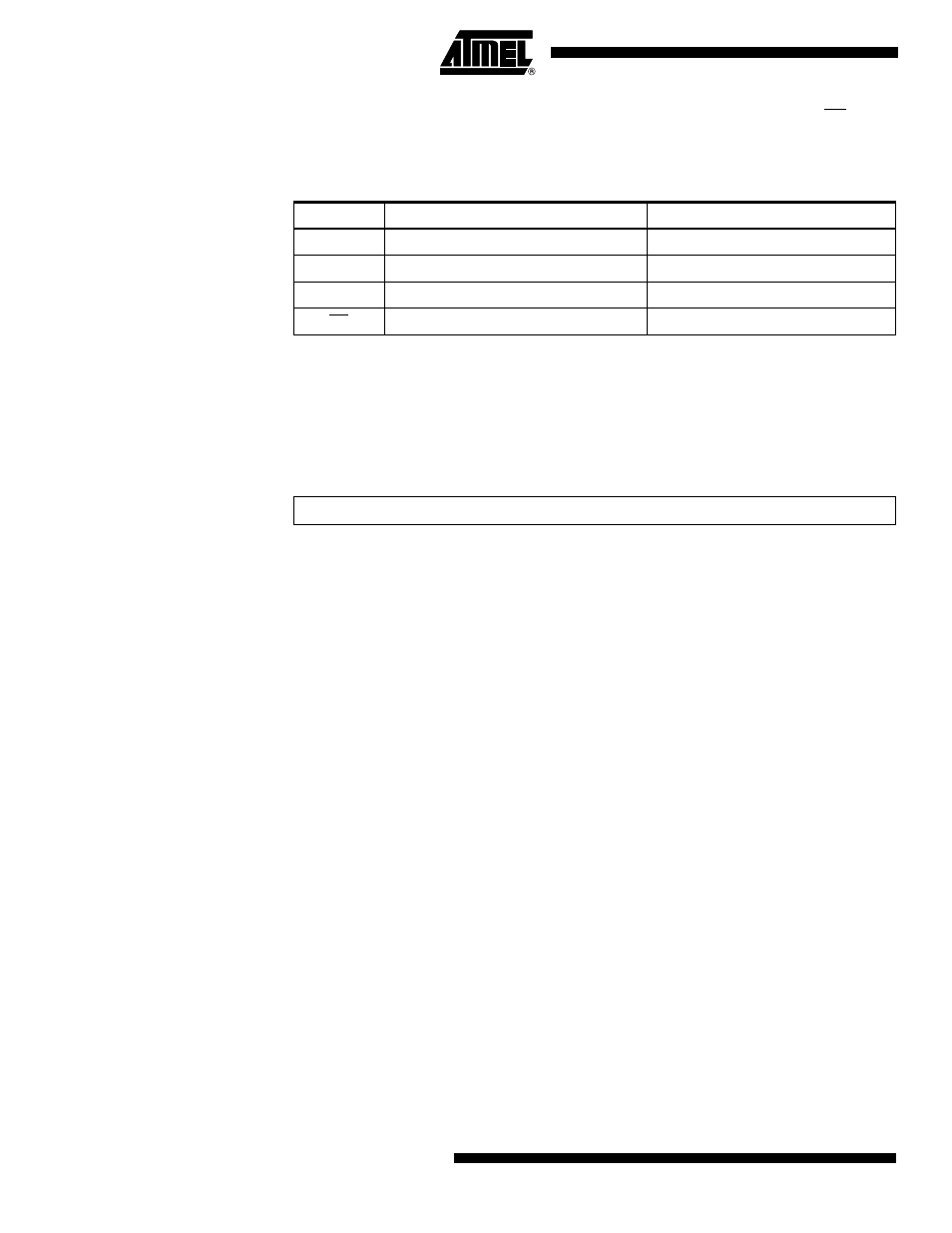
When the SPI is enabled, the data direction of the MOSI, MISO, SCK, and SS pins is
overridden according to Table 72. For more details on automatic port overrides, refer to
“Alternate Port Functions” on page 65.
Note:
1. See “Alternate Functions of Port B” on page 68 for a detailed description of how to
define the direction of the user defined SPI pins.
The following code examples show how to initialize the SPI as a Master and how to per-
form a simple transmission. DDR_SPI in the examples must be replaced by the actual
Data Direction Register controlling the SPI pins. DD_MOSI, DD_MISO and DD_SCK
must be replaced by the actual data direction bits for these pins. E.g. if MOSI is placed
on pin PB5, replace DD_MOSI with DDB5 and DDR_SPI with DDRB.
Table 72. SPI Pin Overrides
Pin
Direction, Master SPI
Direction, Slave SPI
MOSI
User Defined
Input
MISO
Input
User Defined
SCK
User Defined
Input
SS
User Defined
Input
Assembly Code Example
(1)
- MAX5151 (16 pages)
- MAXQ3108 (64 pages)
- MAX5661 (39 pages)
- MAX6691 (7 pages)
- MAX5362 (12 pages)
- ADC10158 (26 pages)
- MAX8922L (14 pages)
- MAX8596Z (8 pages)
- MAX7491 (18 pages)
- MAX15040 (15 pages)
- MAX5177 (16 pages)
- ADC08138 (22 pages)
- MAX5961 (42 pages)
- T89C51RD2 (86 pages)
- MAX16055 (9 pages)
- MAX6659 (17 pages)
- ADC0820 (20 pages)
- MAX6678 (19 pages)
- MAX8884Z (15 pages)
- MAX16915 (9 pages)
- MAX8620 (18 pages)
- MAX5144 (12 pages)
- MAX6670 (8 pages)
- MAX8760 (39 pages)
- W78C32C (14 pages)
- MX7533 (8 pages)
- MAX8727 (13 pages)
- MAX9053 (15 pages)
- W78C54 (16 pages)
- MAX8614B (15 pages)
- W90N740 (219 pages)
- MAX6626 (13 pages)
- ADC10738 (30 pages)
- MAX17000 (31 pages)
- MAX5051 (21 pages)
- MAXQ1004 (18 pages)
- MAX6871 (51 pages)
- MX7847 (12 pages)
- MAX6608 (6 pages)
- MAX17083 (15 pages)
- MAX6641 (17 pages)
- MAX5251 (16 pages)
- MAX6338 (8 pages)
- MAX6690 (16 pages)
- MAX8668 (18 pages)