Timer/counter prescaler – Rainbow Electronics ATmega3290P_V User Manual
Page 150
150
ATmega329/3290/649/6490
2552H–AVR–11/06
(Timer/Counter2 Compare match Interrupt Enable), and OCF2A are set (one), the
Timer/Counter2 Compare match Interrupt is executed.
• Bit 0 – TOV2: Timer/Counter2 Overflow Flag
The TOV2 bit is set (one) when an overflow occurs in Timer/Counter2. TOV2 is cleared
by hardware when executing the corresponding interrupt handling vector. Alternatively,
TOV2 is cleared by writing a logic one to the flag. When the SREG I-bit, TOIE2A
(Timer/Counter2 Overflow Interrupt Enable), and TOV2 are set (one), the
Timer/Counter2 Overflow interrupt is executed. In PWM mode, this bit is set when
Timer/Counter2 changes counting direction at 0x00.
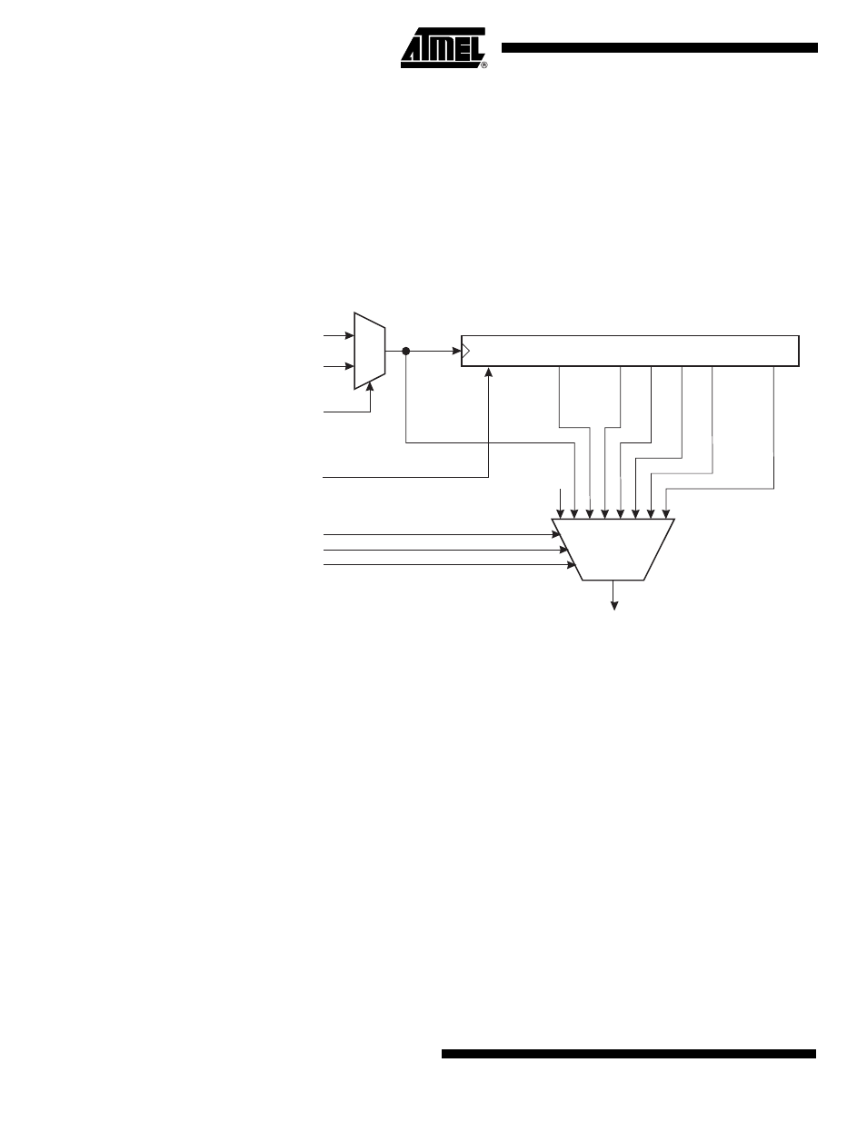
Timer/Counter Prescaler
Figure 65. Prescaler for Timer/Counter2
The clock source for Timer/Counter2 is named clk
T2S
. clk
T2S
is by default connected to
the main system I/O clock clk
IO
. By setting the AS2 bit in ASSR, Timer/Counter2 is asyn-
chronously clocked from the TOSC1 pin. This enables use of Timer/Counter2 as a Real
Time Counter (RTC). When AS2 is set, pins TOSC1 and TOSC2 are disconnected from
Port C. A crystal can then be connected between the TOSC1 and TOSC2 pins to serve
as an independent clock source for Timer/Counter2. The Oscillator is optimized for use
with a 32.768 kHz crystal. If applying an external clock on TOSC1, the EXCLK bit in
ASSR must be set.
For Timer/Counter2, the possible prescaled selections are: clk
T2S
/8, clk
T2S
/32, clk
T2S
/64,
clk
T2S
/128, clk
T2S
/256, and clk
T2S
/1024. Additionally, clk
T2S
as well as 0 (stop) may be
selected. Setting the PSR2 bit in GTCCR resets the prescaler. This allows the user to
operate with a predictable prescaler.
10-BIT T/C PRESCALER
TIMER/COUNTER2 CLOCK SOURCE
clk
I/O
clk
T2S
TOSC1
AS2
CS20
CS21
CS22
clk
T2S
/8
clk
T2S
/64
clk
T2S
/128
clk
T2S
/1024
clk
T2S
/256
clk
T2S
/32
0
PSR2
Clear
clk
T2