Rainbow Electronics ATmega3290P_V User Manual
Page 27
27
ATmega329/3290/649/6490
2552H–AVR–11/06
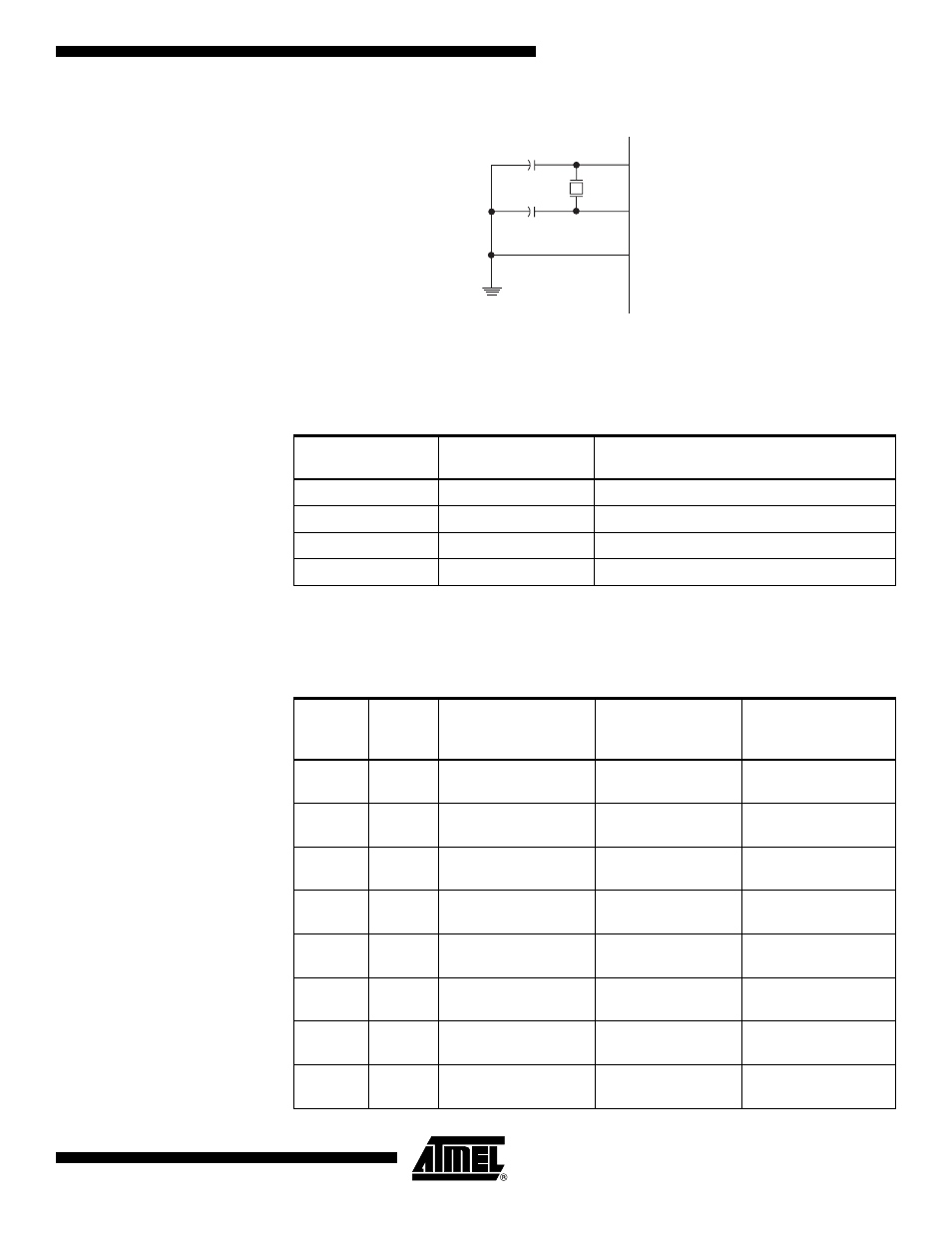
Figure 13. Crystal Oscillator Connections
The Oscillator can operate in three different modes, each optimized for a specific fre-
quency range. The operating mode is selected by the fuses CKSEL3..1 as shown in
Table 5.
Notes:
1. This option should not be used with crystals, only with ceramic resonators.
The CKSEL0 Fuse together with the SUT1..0 Fuses select the start-up times as shown
in Table 6.
Table 5. Crystal Oscillator Operating Modes
CKSEL3..1
Frequency Range
(MHz)
Recommended Range for Capacitors C1
and C2 for Use with Crystals (pF)
100
(1)
0.4 - 0.9
–
101
0.9 - 3.0
12 - 22
110
3.0 - 8.0
12 - 22
111
8.0 -
12 - 22
Table 6. Start-up Times for the Crystal Oscillator Clock Selection
CKSEL0
SUT1..0
Start-up Time from
Power-down and
Power-save
Additional Delay
from Reset
(V
CC
= 5.0V)
Recommended
Usage
0
00
258 CK
(1)
14CK + 4.1 ms
Ceramic resonator,
fast rising power
0
01
258 CK
(1)
14CK + 65 ms
Ceramic resonator,
slowly rising power
0
10
1K CK
(2)
14CK
Ceramic resonator,
BOD enabled
0
11
1K CK
(2)
14CK + 4.1 ms
Ceramic resonator,
fast rising power
1
00
1K CK
(2)
14CK + 65 ms
Ceramic resonator,
slowly rising power
1
01
16K CK
14CK
Crystal Oscillator,
BOD enabled
1
10
16K CK
14CK + 4.1 ms
Crystal Oscillator, fast
rising power
1
11
16K CK
14CK + 65 ms
Crystal Oscillator,
slowly rising power
XTAL2
XTAL1
GND
C2
C1