Lcdfrr - lcd frame rate register – Rainbow Electronics ATmega3290P_V User Manual
Page 232
232
ATmega329/3290/649/6490
2552H–AVR–11/06
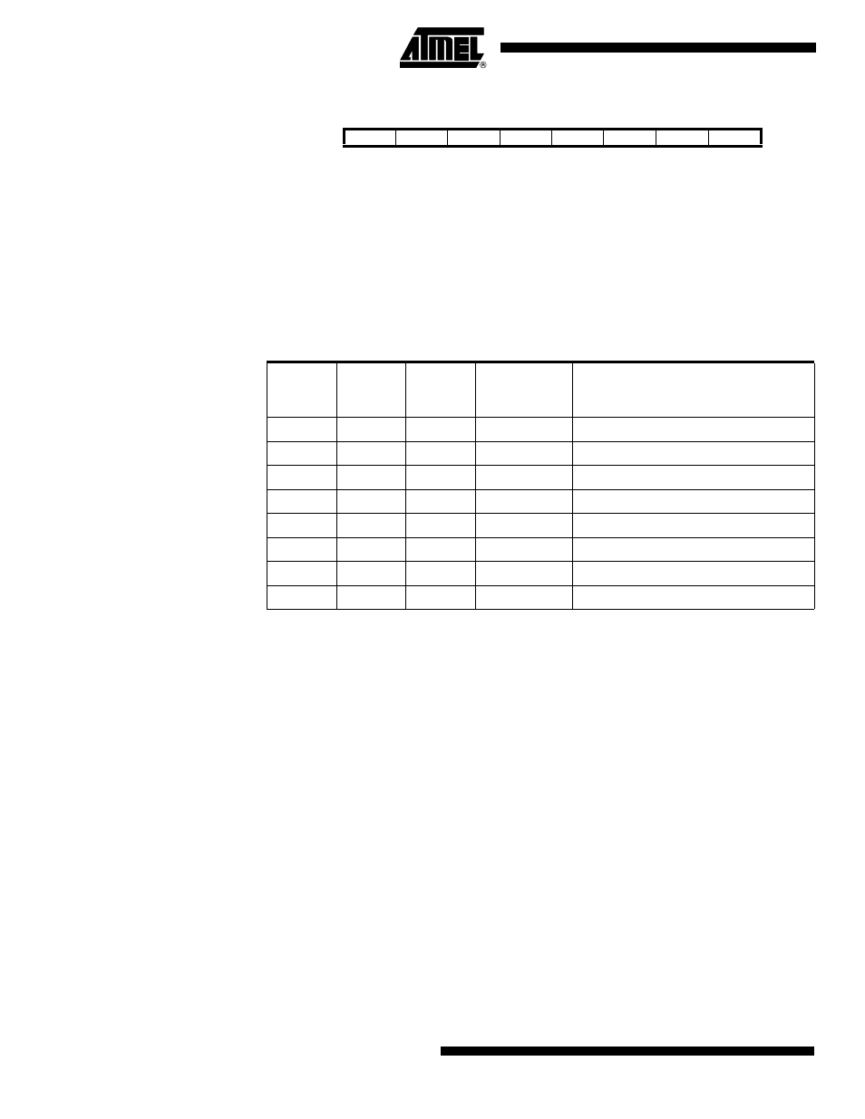
LCDFRR – LCD Frame Rate
Register
• Bit 7 – Res: Reserved Bit
This bit is reserved bit in the ATmega329/3290/649/6490 and will always read as zero.
• Bits 6:4 – LCDPS2:0: LCD Prescaler Select
The LCDPS2:0 bits selects tap point from a prescaler. The prescaled output can be fur-
ther divided by setting the clock divide bits (LCDCD2:0). The different selections are
shown in Table 102. Together they determine the prescaled LCD clock (clk
LCD_PS
),
which is clocking the LCD module.
• Bit 3 – Res: Reserved Bit
This bit is reserved bit in the ATmega329/3290/649/6490 and will always read as zero.
• Bits 2:0 – LCDCD2:0: LCD Clock Divide 2, 1, and 0
The LCDCD2:0 bits determine division ratio in the clock divider. The various selections
are shown in Table 103. This Clock Divider gives extra flexibility in frame rate selection.
Bit
7
6
5
4
3
2
1
0
–
LCDPS2
LCDPS1
LCDPS0
–
LCDCD2
LCDCD1
LCDCD0
LCDFRR
Read/Write
R
R/W
R/W
R/W
R
R/W
R/W
R/W
Initial Value
0
0
0
0
0
0
0
0
Table 102. LCD Prescaler Select
LCDPS2
LCDPS1
LCDPS0
Output from
Prescaler
clk
LCD
/N
Applied Prescaled LCD Clock
Frequency when LCDCD2:0 = 0,
Duty = 1/4, and Frame Rate = 64 Hz
0
0
0
clk
LCD
/16
8.1 kHz
0
0
1
clk
LCD
/64
33 kHz
0
1
0
clk
LCD
/128
66 kHz
0
1
1
clk
LCD
/256
130 kHz
1
0
0
clk
LCD
/512
260 kHz
1
0
1
clk
LCD
/1024
520 kHz
1
1
0
clk
LCD
/2048
1 MHz
1
1
1
clk
LCD
/4096
2 MHz