Reading the fuse and lock bits, Reading the signature bytes, Reading the calibration byte – Rainbow Electronics ATmega3290P_V User Manual
Page 293
293
ATmega329/3290/649/6490
2552H–AVR–11/06
Reading the Fuse and Lock
Bits
The algorithm for reading the Fuse and Lock bits is as follows (refer to “Programming
the Flash” on page 288 for details on Command loading):
1.
A: Load Command “0000 0100”.
2.
Set OE to “0”, BS2 to “0” and BS1 to “0”. The status of the Fuse Low bits can
now be read at DATA (“0” means programmed).
3.
Set OE to “0”, BS2 to “1” and BS1 to “1”. The status of the Fuse High bits can
now be read at DATA (“0” means programmed).
4.
Set OE to “0”, BS2 to “1”, and BS1 to “0”. The status of the Extended Fuse bits
can now be read at DATA (“0” means programmed).
5.
Set OE to “0”, BS2 to “0” and BS1 to “1”. The status of the Lock bits can now be
read at DATA (“0” means programmed).
6.
Set OE to “1”.
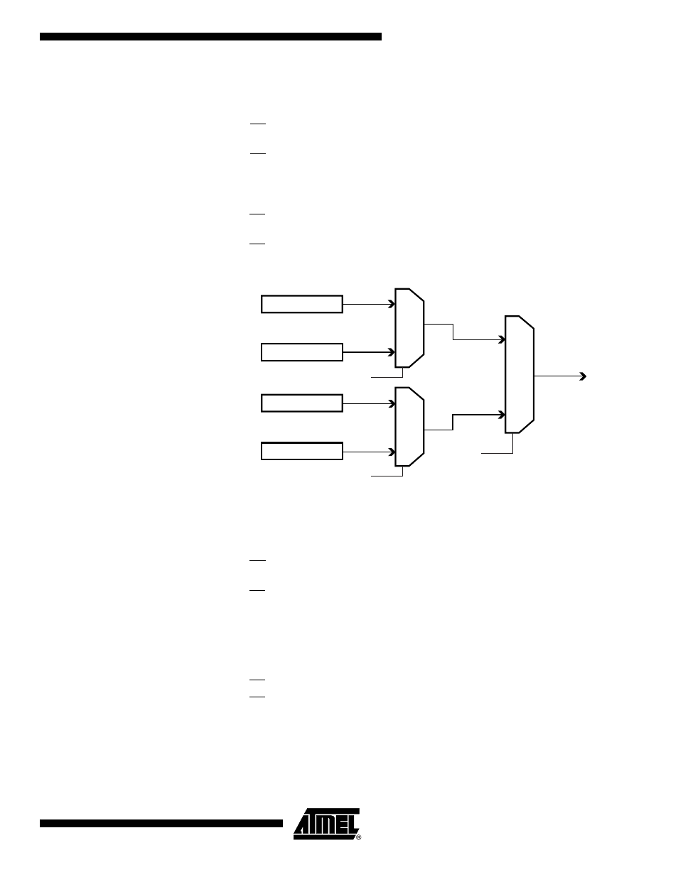
Figure 125. Mapping Between BS1, BS2 and the Fuse and Lock Bits During Read
Reading the Signature Bytes
The algorithm for reading the Signature bytes is as follows (refer to “Programming the
Flash” on page 288 for details on Command and Address loading):
1.
A: Load Command “0000 1000”.
2.
B: Load Address Low Byte (0x00 - 0x02).
3.
Set OE to “0”, and BS1 to “0”. The selected Signature byte can now be read at
DATA.
4.
Set OE to “1”.
Reading the Calibration Byte
The algorithm for reading the Calibration byte is as follows (refer to “Programming the
Flash” on page 288 for details on Command and Address loading):
1.
A: Load Command “0000 1000”.
2.
B: Load Address Low Byte, 0x00.
3.
Set OE to “0”, and BS1 to “1”. The Calibration byte can now be read at DATA.
4.
Set OE to “1”.
Lock Bits
0
1
BS2
Fuse High Byte
0
1
BS1
DATA
Fuse Low Byte
0
1
BS2
Extended Fuse Byte