Power management and sleep modes – Rainbow Electronics ATmega3290P_V User Manual
Page 33
33
ATmega329/3290/649/6490
2552H–AVR–11/06
Power Management
and Sleep Modes
Sleep modes enable the application to shut down unused modules in the MCU, thereby
saving power. The AVR provides various sleep modes allowing the user to tailor the
power consumption to the application’s requirements.
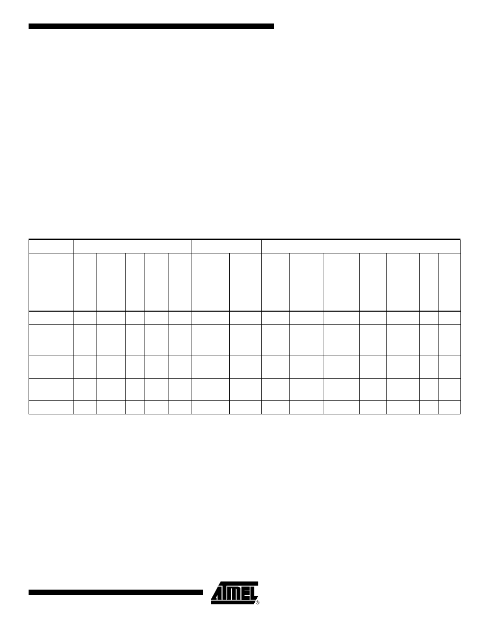
To enter any of the five sleep modes, the SE bit in SMCR must be written to logic one
and a SLEEP instruction must be executed, see “SMCR – Sleep Mode Control Register”
on page 38. The SM2, SM1, and SM0 bits in the SMCR Register select which sleep
mode (Idle, ADC Noise Reduction, Power-down, Power-save, or Standby) will be acti-
vated by the SLEEP instruction. See Table 14 on page 33 for a summary. If an enabled
interrupt occurs while the MCU is in a sleep mode, the MCU wakes up. The MCU is then
halted for four cycles in addition to the start-up time, executes the interrupt routine, and
resumes execution from the instruction following SLEEP. The contents of the Register
File and SRAM are unaltered when the device wakes up from sleep. If a reset occurs
during sleep mode, the MCU wakes up and executes from the Reset Vector.
F i g u r e 1 2 o n p a g e 2 5 p r e s e n t s t h e d i f f e r e n t c l o c k s y s t e m s i n t h e
ATmega329/3290/649/6490, and their distribution. The figure is helpful in selecting an
appropriate sleep mode.
Notes:
1. Only recommended with external crystal or resonator selected as clock source.
2. If either LCD controller or Timer/Counter2 is running in asynchronous mode.
3. For INT0, only level interrupt.
Table 14. Active Clock Domains and Wake-up Sources in the Different Sleep Modes.
Active Clock Domains
Oscillators
Wake-up Sources
Sleep
Mode
clk
CPU
clk
FLASH
clk
IO
clk
AD
C
clk
ASY
Main
Clo
c
k
Sour
ce
Enab
led
Time
r Osc
Enab
led
IN
T0
an
d
Pi
n
Chang
e
USI Star
t
Condition
LC
D
Contr
o
ller
Time
r2
SPM/EEPR
OM
Rea
d
y
ADC
Oth
e
r I
/O
Idle
X
X
X
X
X
(2)
X
X
X
X
X
X
X
ADC
Noise
Reduction
X
X
X
X
(2)
X
(3)
X
X
(2)
X
(2)
X
X
Power-
down
X
(3)
X
Power-
save
X
X
(2)
X
(3)
X
X
X
Standby
(1)
X
X
(3)
X