Low-frequency crystal oscillator, Calibrated internal rc oscillator – Rainbow Electronics ATmega3290P_V User Manual
Page 28
28
ATmega329/3290/649/6490
2552H–AVR–11/06
Notes:
1. These options should only be used when not operating close to the maximum fre-
quency of the device, and only if frequency stability at start-up is not important for the
application. These options are not suitable for crystals.
2. These options are intended for use with ceramic resonators and will ensure fre-
quency stability at start-up. They can also be used with crystals when not operating
close to the maximum frequency of the device, and if frequency stability at start-up is
not important for the application.
Low-frequency Crystal
Oscillator
To use a 32.768 kHz watch crystal as the clock source for the device, the low-frequency
crystal Oscillator must be selected by setting the CKSEL Fuses to “0110” or “0111”. The
crystal should be connected as shown in Figure 13. When this Oscillator is selected,
start-up times are determined by the SUT Fuses as shown in Table 7 and CKSEL1..0 as
shown in Table 8.
Note:
1. This option should only be used if frequency stability at start-up is not important for
the application
Calibrated Internal RC
Oscillator
The calibrated Internal RC Oscillator by default provides a 8.0 MHz clock. The fre-
quency is nominal value at 3V and 25°C. The device is shipped with the CKDIV8 Fuse
programmed. See “System Clock Prescaler” on page 31 for more details.
This clock may be selected as the system clock by programming the CKSEL Fuses as
shown in Table 9 on page 29. If selected, it will operate with no external components.
During reset, hardware loads the pre-programmed calibration value into the OSCCAL
Register and thereby automatically calibrates the RC Oscillator. The accuracy of this
calibration is shown as Factory calibration in Table 143 on page 319.
By changing the OSCCAL register from SW, see “OSCCAL – Oscillator Calibration Reg-
ister” on page 29, it is possible to get a higher calibration accuracy than by using the
factory calibration. The accuracy of this calibration is shown as User calibration in Table
143 on page 319.
When this Oscillator is used as the chip clock, the Watchdog Oscillator will still be used
for the Watchdog Timer and for the Reset Time-out. For more information on the pre-
programmed calibration value, see the section “Calibration Byte” on page 284.
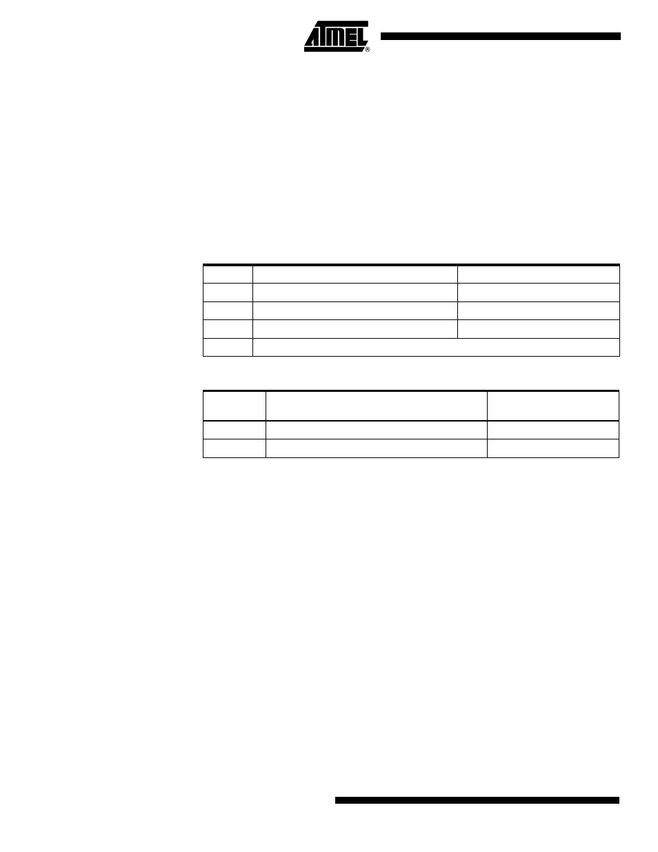
Table 7. Start-up Times for the Low-frequency Crystal Oscillator Clock Selection
SUT1..0
Additional Delay from Reset (V
CC
= 5.0V)
Recommended Usage
00
14CK
Fast rising power or BOD enabled
01
14CK + 4.1 ms
Slowly rising power
10
14CK + 65 ms
Stable frequency at start-up
11
Reserved
Table 8. Start-up Times for the Low-frequency Crystal Oscillator Clock Selection
CKSEL3..0
Start-up Time from
Power-down and Power-save
Recommended Usage
0110
(1)
1K CK
0111
32K CK
Stable frequency at start-up