Register description, Smcr - sleep mode control register, Prr - power reduction register – Rainbow Electronics ATmega3290P_V User Manual
Page 38
38
ATmega329/3290/649/6490
2552H–AVR–11/06
Register Description
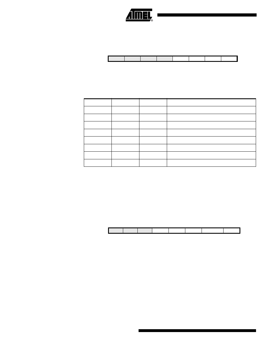
SMCR – Sleep Mode Control
Register
The Sleep Mode Control Register contains control bits for power management.
• Bits 3, 2, 1 – SM2:0: Sleep Mode Select Bits 2, 1, and 0
These bits select between the five available sleep modes as shown in Table 15.
Note:
1. Standby mode is only recommended for use with external crystals or resonators.
• Bit 1 – SE: Sleep Enable
The SE bit must be written to logic one to make the MCU enter the sleep mode when the
SLEEP instruction is executed. To avoid the MCU entering the sleep mode unless it is
the programmer’s purpose, it is recommended to write the Sleep Enable (SE) bit to one
just before the execution of the SLEEP instruction and to clear it immediately after wak-
ing up.
PRR – Power Reduction
Register
• Bits 7, 6, 5 - Res: Reserved bits
These bits are reserved bits in ATmega329/3290/649/6490 and will always read as
zero.
• Bit 4 - PRLCD: Power Reduction LCD
Writing logic one to this bit shuts down the LCD controller. The LCD controller must be
disabled and the display discharged before shut down. See "Disabling the LCD" on
page 217 for details on how to disable the LCD controller.
• Bit 3 - PRTIM1: Power Reduction Timer/Counter1
Writing logic one to this bit shuts down the Timer/Counter1 module. When
Timer/Counter1 is enabled, operation will continue like before the shutdown.
• Bit 2 - PRSPI: Power Reduction Serial Peripheral Interface
Bit
7
6
5
4
3
2
1
0
–
–
–
–
SM2
SM1
SM0
SE
SMCR
Read/Write
R
R
R
R
R/W
R/W
R/W
R/W
Initial Value
0
0
0
0
0
0
0
0
Table 15. Sleep Mode Select
SM2
SM1
SM0
Sleep Mode
0
0
0
Idle
0
0
1
ADC Noise Reduction
0
1
0
Power-down
0
1
1
Power-save
1
0
0
Reserved
1
0
1
Reserved
1
1
0
Standby
(1)
1
1
1
Reserved
Bit
7
6
5
4
3
2
1
0
–
–
–
PRLCD
PRTIM1
PRSPI
PRUSART0
PRADC
PRR
Read/Write
R
R
R
R/W
R/W
R/W
R/W
R/W
Initial Value
0
0
0
0
0
0
0
0