Ucsrnc - usart control and status register n c – Rainbow Electronics ATmega3290P_V User Manual
Page 181
181
ATmega329/3290/649/6490
2552H–AVR–11/06
• Bit 3 – TXENn: Transmitter Enable
Writing this bit to one enables the USART Transmitter. The Transmitter will override nor-
mal port operation for the TxD pin when enabled. The disabling of the Transmitter
(writing TXENn to zero) will not become effective until ongoing and pending transmis-
sions are completed, i.e., when the Transmit Shift Register and Transmit Buffer Register
do not contain data to be transmitted. When disabled, the Transmitter will no longer
override the TxD port.
• Bit 2 – UCSZn2: Character Size
The UCSZn2 bits combined with the UCSZn1:0 bit in UCSRnC sets the number of data
bits (Character SiZe) in a frame the Receiver and Transmitter use.
• Bit 1 – RXB8n: Receive Data Bit 8
RXB8n is the ninth data bit of the received character when operating with serial frames
with nine data bits. Must be read before reading the low bits from UDRn.
• Bit 0 – TXB8n: Transmit Data Bit 8
TXB8n is the ninth data bit in the character to be transmitted when operating with serial
frames with nine data bits. Must be written before writing the low bits to UDRn.
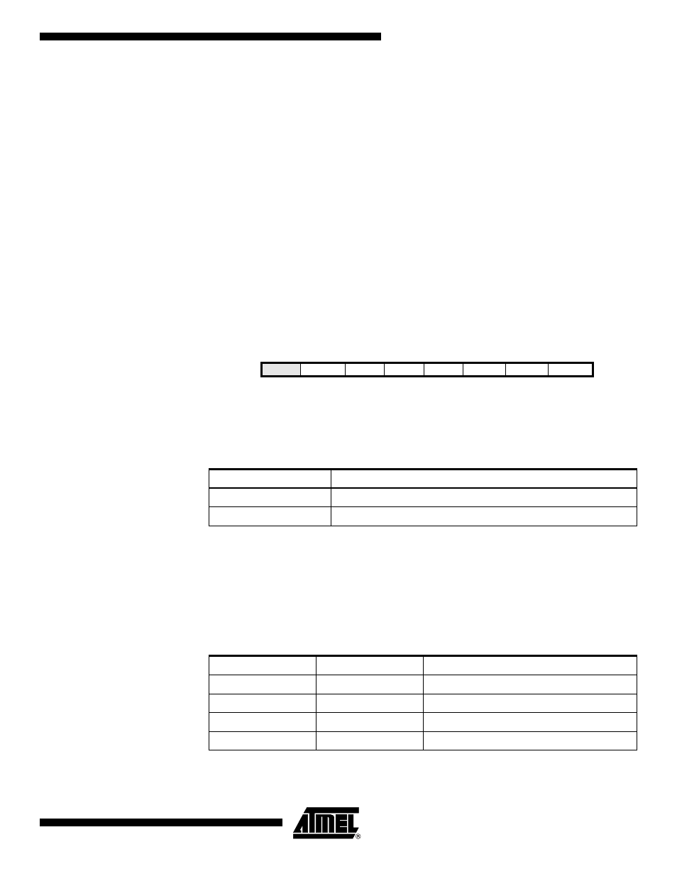
UCSRnC – USART Control
and Status Register n C
• Bit 6 – UMSELn: USART Mode Select
This bit selects between asynchronous and synchronous mode of operation.
• Bit 5:4 – UPMn1:0: Parity Mode
These bits enable and set type of parity generation and check. If enabled, the Transmit-
ter will automatically generate and send the parity of the transmitted data bits within
each frame. The Receiver will generate a parity value for the incoming data and com-
pare it to the UPMn0 setting. If a mismatch is detected, the UPEn Flag in UCSRnA will
be set.
Bit
7
6
5
4
3
2
1
0
–
UMSELn
UPMn1
UPMn0
USBSn
UCSZn1
UCSZn0
UCPOLn
UCSRnC
Read/Write
R
R/W
R/W
R/W
R/W
R/W
R/W
R/W
Initial Value
0
0
0
0
0
1
1
0
Table 80. UMSELn Bit Settings
UMSELn
Mode
0
Asynchronous Operation
1
Synchronous Operation
Table 81. UPMn Bits Settings
UPMn1
UPMn0
Parity Mode
0
0
Disabled
0
1
Reserved
1
0
Enabled, Even Parity
1
1
Enabled, Odd Parity