Mcusr - mcu status register – Rainbow Electronics ATmega3290P_V User Manual
Page 44
44
ATmega329/3290/649/6490
2552H–AVR–11/06
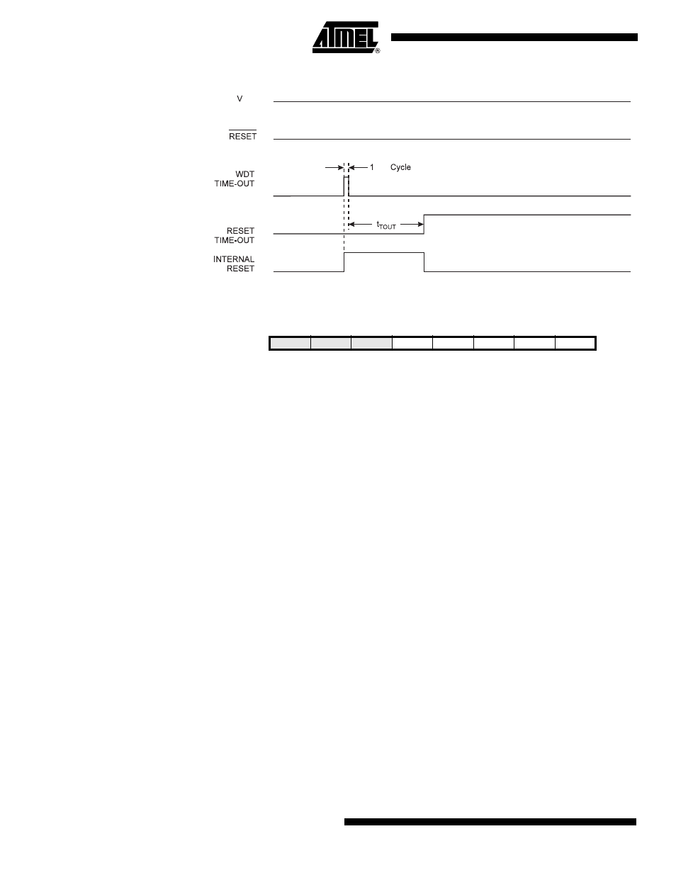
Figure 20. Watchdog Reset During Operation
MCUSR – MCU Status
Register
The MCU Status Register provides information on which reset source caused an MCU
reset.
• Bit 4 – JTRF: JTAG Reset Flag
This bit is set if a reset is being caused by a logic one in the JTAG Reset Register
selected by the JTAG instruction AVR_RESET. This bit is reset by a Power-on Reset, or
by writing a logic zero to the flag.
• Bit 3 – WDRF: Watchdog Reset Flag
This bit is set if a Watchdog Reset occurs. The bit is reset by a Power-on Reset, or by
writing a logic zero to the flag.
• Bit 2 – BORF: Brown-out Reset Flag
This bit is set if a Brown-out Reset occurs. The bit is reset by a Power-on Reset, or by
writing a logic zero to the flag.
• Bit 1 – EXTRF: External Reset Flag
This bit is set if an External Reset occurs. The bit is reset by a Power-on Reset, or by
writing a logic zero to the flag.
• Bit 0 – PORF: Power-on Reset Flag
This bit is set if a Power-on Reset occurs. The bit is reset only by writing a logic zero to
the flag.
To make use of the Reset Flags to identify a reset condition, the user should read and
then Reset the MCUSR as early as possible in the program. If the register is cleared
before another reset occurs, the source of the reset can be found by examining the
Reset Flags.
CK
CC
Bit
7
6
5
4
3
2
1
0
–
–
–
JTRF
WDRF
BORF
EXTRF
PORF
MCUSR
Read/Write
R
R
R
R/W
R/W
R/W
R/W
R/W
Initial Value
0
0
0
See Bit Description