Power-on reset – Rainbow Electronics ATmega3290P_V User Manual
Page 41
41
ATmega329/3290/649/6490
2552H–AVR–11/06
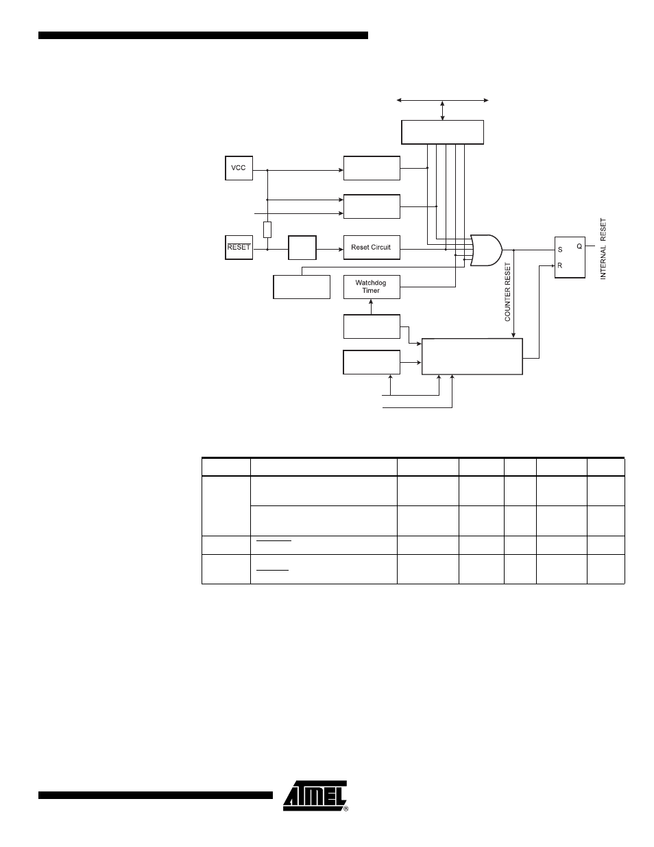
Figure 15. Reset Logic
Notes:
1. The Power-on Reset will not work unless the supply voltage has been below V
POT
(falling)
Power-on Reset
A Power-on Reset (POR) pulse is generated by an On-chip detection circuit. The detec-
tion level is defined in Table 16. The POR is activated whenever V
CC
is below the
detection level. The POR circuit can be used to trigger the start-up Reset, as well as to
detect a failure in supply voltage.
A Power-on Reset (POR) circuit ensures that the device is reset from Power-on. Reach-
ing the Power-on Reset threshold voltage invokes the delay counter, which determines
how long the device is kept in RESET after V
CC
rise. The RESET signal is activated
again, without any delay, when V
CC
decreases below the detection level.
Table 16. Reset Characteristics
Symbol
Parameter
Condition
Min
Typ
Max
Units
V
POT
Power-on Reset Threshold
Voltage (rising)
T
A
= -40°C
to 85°C
0.7
1.0
1.4
V
Power-on Reset Threshold
Voltage (falling)
(1)
T
A
= -40°C
to 85°C
0.6
0.9
1.3
V
V
RST
RESET Pin Threshold Voltage
V
CC
= 3V
0.2 V
CC
0.85 V
CC
V
t
RST
Minimum pulse width on
RESET Pin
V
CC
= 3V
800
ns
MCU Status
Register (MCUSR)
Brown-out
Reset Circuit
BODLEVEL [1..0]
Delay Counters
CKSEL[3:0]
CK
TIMEOUT
WDRF
BORF
EXTRF
PORF
DATA BUS
Clock
Generator
SPIKE
FILTER
Pull-up Resistor
JTRF
JTAG Reset
Register
Watchdog
Oscillator
SUT[1:0]
Power-on Reset
Circuit