Ubrrnl and ubrrnh - usart baud rate registers n – Rainbow Electronics ATmega3290P_V User Manual
Page 182
182
ATmega329/3290/649/6490
2552H–AVR–11/06
• Bit 3 – USBSn: Stop Bit Select
This bit selects the number of stop bits to be inserted by the Transmitter. The Receiver
ignores this setting.
• Bit 2:1 – UCSZn1:0: Character Size
The UCSZn1:0 bits combined with the UCSZn2 bit in UCSRnB sets the number of data
bits (Character SiZe) in a frame the Receiver and Transmitter use.
• Bit 0 – UCPOLn: Clock Polarity
This bit is used for synchronous mode only. Write this bit to zero when asynchronous
mode is used. The UCPOLn bit sets the relationship between data output change and
data input sample, and the synchronous clock (XCK).
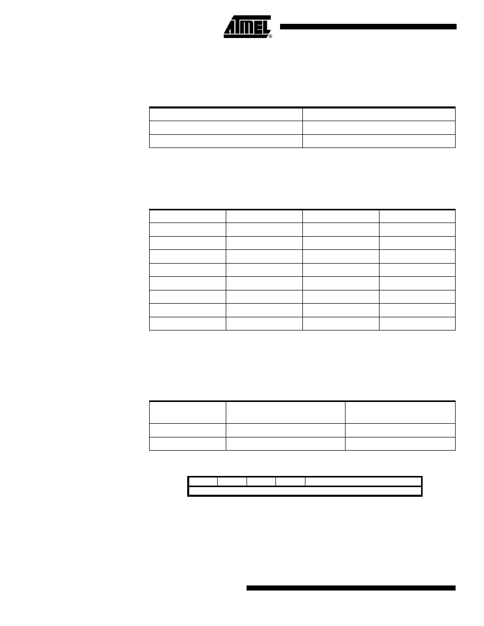
UBRRnL and UBRRnH –
USART Baud Rate Registers n
Table 82. USBSn Bit Settings
USBSn
Stop Bit(s)
0
1-bit
1
2-bit
Table 83. UCSZ Bits Settings
UCSZn2
UCSZn1
UCSZn0
Character Size
0
0
0
5-bit
0
0
1
6-bit
0
1
0
7-bit
0
1
1
8-bit
1
0
0
Reserved
1
0
1
Reserved
1
1
0
Reserved
1
1
1
9-bit
Table 84. UCPOLn Bit Settings
UCPOLn
Transmitted Data Changed
(Output of TxD Pin)
Received Data Sampled
(Input on RxD Pin)
0
Rising XCK Edge
Falling XCK Edge
1
Falling XCK Edge
Rising XCK Edge
Bit
15
14
13
12
11
10
9
8
–
–
–
–
UBRRn[11:8]
UBRRnH
UBRRn[7:0]
UBRRnL
7
6
5
4
3
2
1
0
Read/Write
R
R
R
R
R/W
R/W
R/W
R/W
R/W
R/W
R/W
R/W
R/W
R/W
R/W
R/W
Initial Value
0
0
0
0
0
0
0
0
0
0
0
0
0
0
0
0