Rainbow Electronics ATmega3290P_V User Manual
Page 231
231
ATmega329/3290/649/6490
2552H–AVR–11/06
either Timer/Counter Oscillator or external clock, depending on EXCLK in ASSR. See
“Asynchronous operation of the Timer/Counter” on page 147 for further details.
• Bit 6 – LCD2B: LCD 1/2 Bias Select
When this bit is written to zero, 1/3 bias is used. When this bit is written to one, ½ bias is
used. Refer to the LCD Manufacture for recommended bias selection.
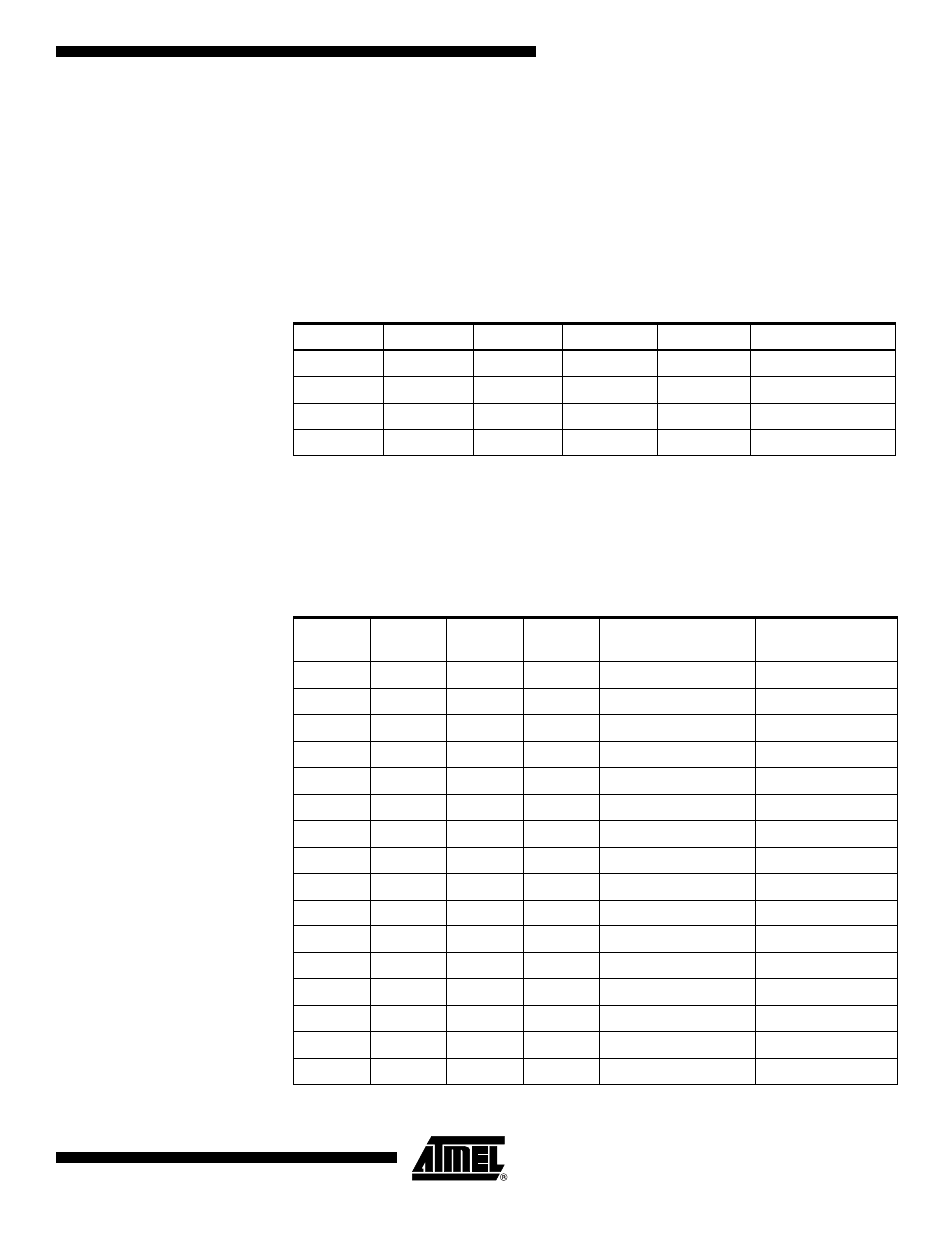
• Bit 5:4 – LCDMUX1:0: LCD Mux Select
The LCDMUX1:0 bits determine the duty cycle. Common pins that are not used are ordi-
nary port pins. The different duty selections are shown in Table 100.
Note:
1. 1/2 bias when LCD2B is written to one and 1/3 otherwise.
• Bits 3:0 – LCDPM3:0: LCD Port Mask
The LCDPM3:0 bits determine the number of port pins to be used as segment drivers.
The different selections are shown in Table 101. Unused pins can be used as ordinary
port pins.
Note:
1. LCDPM3 is reserved and will always read as zero in ATmega329/649.
Table 100. LCD Duty Select
LCDMUX1
LCDMUX0
Duty
Bias
COM Pin
I/O Port Pin
0
0
Static
Static
COM0
COM1:3
0
1
1/2
1/2 or 1/3
(1)
COM0:1
COM2:3
1
0
1/3
1/2
or 1/3
(1)
COM0:2
COM3
1
1
1/4
1/2
or 1/3
(1)
COM0:3
None
Table 101. LCD Port Mask (Values in bold are only available in ATmega3290/6490)
LCDPM3
LCDPM2
LCDPM1
LCDPM0
I/O Port in Use as
Segment Driver
Maximum Number
of Segments
0
0
0
0
SEG0:12
13
0
0
0
1
SEG0:14
15
0
0
1
0
SEG0:16
17
0
0
1
1
SEG0:18
19
0
1
0
0
SEG0:20
21
0
1
0
1
SEG0:22
23
0
1
1
0
SEG0:23
24
0
1
1
1
SEG0:24
25
1
0
0
0
SEG0:26
27
1
0
0
1
SEG0:28
29
1
0
1
0
SEG0:30
31
1
0
1
1
SEG0:32
33
1
1
0
0
SEG0:34
35
1
1
0
1
SEG0:36
37
1
1
1
0
SEG0:38
39
1
1
1
1
SEG0:39
40