Watchdog reset – Rainbow Electronics ATmega3290P_V User Manual
Page 43
43
ATmega329/3290/649/6490
2552H–AVR–11/06
teresis to ensure spike free Brown-out Detection. The hysteresis on the detection level
should be interpreted as V
BOT+
= V
BOT
+ V
HYST
/2 and V
BOT-
= V
BOT
- V
HYST
/2.
Note:
1. V
BOT
may be below nominal minimum operating voltage for some devices. For
devices where this is the case, the device is tested down to V
CC
= V
BOT
during the
production test. This guarantees that a Brown-Out Reset will occur before V
CC
drops
to a voltage where correct operation of the microcontroller is no longer guaranteed.
The test is performed using BODLEVEL = 10 for ATmega329/3290/649/6490V and
BODLEVEL = 01 for ATmega329/3290/649/6490L.
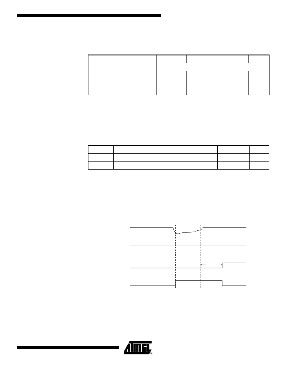
When the BOD is enabled, and V
CC
decreases to a value below the trigger level (V
BOT-
in Figure 19), the Brown-out Reset is immediately activated. When V
CC
increases above
the trigger level (V
BOT+
in Figure 19), the delay counter starts the MCU after the Time-
out period t
TOUT
has expired.
The BOD circuit will only detect a drop in V
CC
if the voltage stays below the trigger level
for longer than t
BOD
given in Table 16.
Figure 19. Brown-out Reset During Operation
Watchdog Reset
When the Watchdog times out, it will generate a short reset pulse of one CK cycle dura-
tion. On the falling edge of this pulse, the delay timer starts counting the Time-out period
t
TOUT
. Refer to page 45 for details on operation of the Watchdog Timer.
Table 17. BODLEVEL Fuse Coding
(1)
BODLEVEL 2:0 Fuses
Min V
BOT
Typ V
BOT
Max V
BOT
Units
11
BOD Disabled
10
1.8
V
01
2.7
00
4.3
Table 18. Brown-out Characteristics
Symbol
Parameter
Min
Typ
Max
Units
V
HYST
Brown-out Detector Hysteresis
50
mV
t
BOD
Min Pulse Width on Brown-out Reset
2
µs
V
CC
RESET
TIME-OUT
INTERNAL
RESET
V
BOT-
V
BOT+
t
TOUT