Rainbow Electronics W90N740 User Manual
Page 38
W90N740
- 34 -
WDT [8] : WDT clock enable bit
0 = Disable WDT counting clock
1 = Enable WDT counting clock
USB [7] : USB clock enable bit
0 = Disable USB clock
1 = Enable USB clock
TIMER [6] : Timer clock enable bit
0 = Disable Timer clock
1 = Enable Timer clock
UART [5] : UART clock enable bit
0 = Disable UART clock
1 = Enable UART clock
ECLKS [4] : External clock select
0 = External clock from EXTAL pin is used as system clock
1 = PLL output clock is used as system clock
After power on reset, the content of ECLKS is the Power-On Setting value. You can program this bit to
change the system clock source.
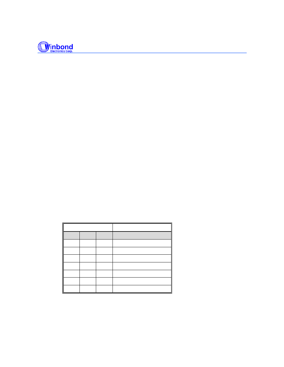
CLKS [3:1] : PLL output clock select
CLKS [3:1]
PLL output clock
0
0
0
58.594 KHz*
0 0 1
24
MHz
0 1 0
48
MHz
0 1 1
60
MHz
1 0 0
80
MHz
1 0 1
RESERVED
1 1 0
RESERVED
1 1 1
RESERVED
When 24Mhz ~ 120MHz is setting, the ECLKS bit is needed to set on PLL output clock mode (logic 1).
*About 58.594KHz setting, two steps are needed.
First step, the ECLKS bit is set to External Clock mode (logic 0, 15MHz), then set CLKS bits to 0.