Rainbow Electronics W90N740 User Manual
Page 171
W90N740
Publication Release Date: November 26, 2004
- 167 -
Revision A4
0 = Disables timer interrupt
1 = Enables timer interrupt. If timer interrupt is enabled, the timer asserts its interrupt signal when the
associated counter decrements to zero.
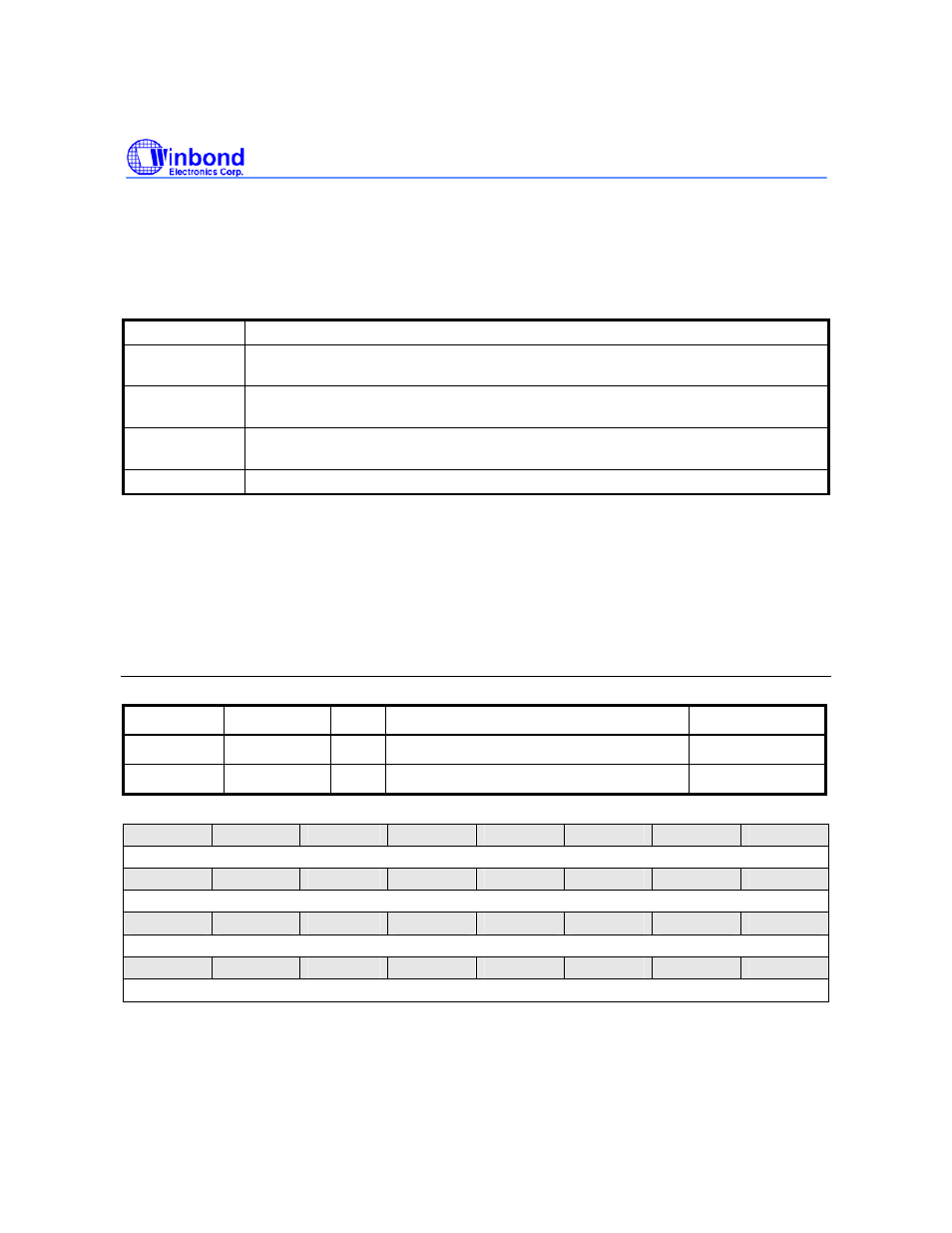
MODE [28:27]: Timer Operating Mode
MODE [28:27]
Timer Operating Mode
00
The timer is operating in the one-shot mode. The associated interrupt signal is
generated once (if IE is enabled) and CE is automatically cleared then.
01
The timer is operating in the periodic mode. The associated interrupt signal is
generated periodically (if IE is enabled).
10
The timer is operating in the toggle mode. The associated interrupt signal is
changing back and forth (if IE is enabled) with 50% duty cycle.
11
Reserved for further use
PRESCALE [7:0]
Clock input is divided by PRESCALE + 1 before it is fed to the counter (here PRESCALE is considered
as a decimal number). If PRESCALE = 0, then there is no scaling.
Timer Initial Count Register 0 (TICR0)
Timer Initial Count Register 1 (TICR1)
Register Address
R/W/C
Description
Reset
Value
TICR0
0xFFF8.1008 R/W Timer Initial Control Register 0
0x0000.00FF
TICR1
0xFFF8.100C R/W Timer Initial Control Register 1
0x0000.00FF
31
30
29
28
27
26
25
24
RESERVED
23
22
21
20
19
18
17
16
TIC [23:16]
15
14
13
12
11
10
9
8
TIC [15:8]
7
6
5
4
3
2
1
0
TIC [7:0]