Rainbow Electronics W90N740 User Manual
Page 195
W90N740
Publication Release Date: November 26, 2004
- 191 -
Revision A4
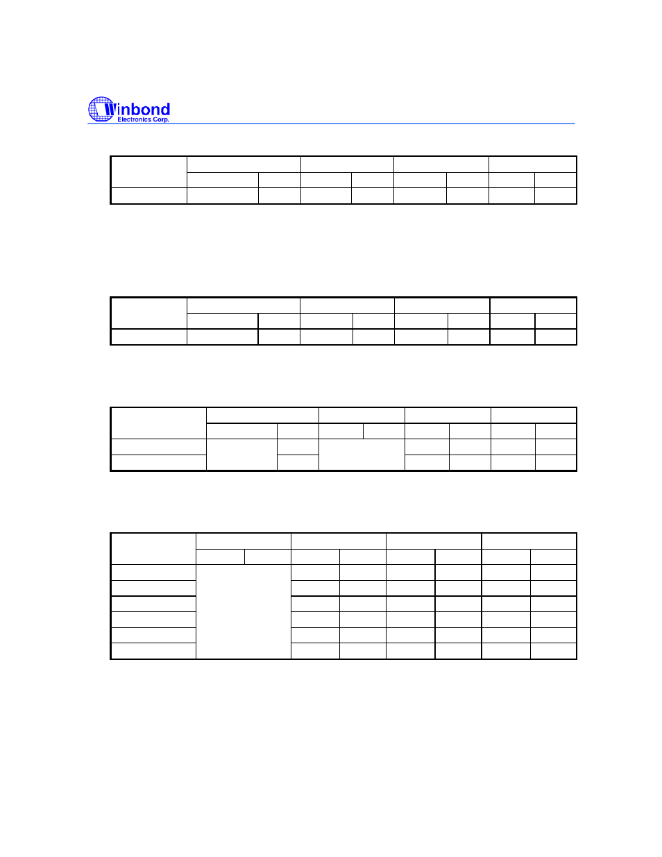
GPIOCFG13 [9:8]: Operating mode for GPIO13
11 10
01
00
GPIOCFG13
Name Type
Name
Type
Name
Type
Name
Type
GPIO13
RESERVED O STDBY
O TIMER0
O GP13 IO
STDBY is a USB IO port, which controls the external USB transceiver power-down mode.
TIMER0 is the tone output of TIMER0.
GPIOCFG12 [7:6]: Operating mode for GPIO12
11 10
01
00
GPIOCFG12
Name Type
Name
Type
Name
Type
Name
Type
GPIO12
RESERVED IO PWREN
IO nWDOG
O GP12 IO
nWDOG is the timeout output of Watch-Dog Timer.
GPIOCFG11_10 [5:4]: Operating mode for GPIO11 and GPIO10
11
10 01 00
GPIOCFG11_10
Name
Type
Name
Type
Name
Type Name Type
GPIO11
O RxD
I
GP11
IO
GPIO10
RESERVED
O
RESERVED
TxD O GP10 IO
RxD and TxD are used for the UART console.
GPIOCFG9_4 [3:2]: Operating mode for GPIO9, GPIO8, GPIO7, GPIO6, GPIO5, and GPIO4
11 10 01 00
GPIOCFG9_4
Name Type Name
Type Name
Type Name Type
GPIO9
nTOE O nDSR
IU GP9 IOU
GPIO8
FSE0 O nDTR O GP8 IOU
GPIO7
VO O nCD IU GP7
IOU
GPIO6
VM IU nCTS IU GP6
IOU
GPIO5
VP IU
nRTS O GP5
IOU
GPIO4
RESERVED
RCV IU nRI IU GP4
IOU
nTOE, FSE0, VO, VM, VP, and RCV are the USB IO signal pins, which connected to the external
USB transceiver to control the data in/out.
nDSR, nDTR, nCD, nCTS, nRTS and nRI are the UART modem signal pins.