Rainbow Electronics W90N740 User Manual
Page 167
W90N740
Publication Release Date: November 26, 2004
- 163 -
Revision A4
PEI [2]: Parity Error Indicator
This bit is set to logic 1 whenever the received character does not have a valid "parity bit", and is reset
whenever the CPU reads the contents of the LSR.
OEI [1]: Overrun Error Indicator
An overrun error will occur only after the RX FIFO is full and the next character has been completely
received in the shift register. The character in the shift register is overwritten, but it is not transferred to
the RX FIFO. OE is indicated to the CPU as soon as it happens and is reset whenever the CPU reads
the contents of the LSR.
RFDR [0]: RX FIFO Data Ready
0 = RX FIFO is empty
1 = RX FIFO contains at least 1 received data word.
LSR [4:2] (BII, FEI, PEI) are revealed to the CPU when its associated character is at the top of the RX
FIFO. These three error indicators are reset whenever the CPU reads the contents of the LSR.
LSR [4:1] (BII, FEI, PEI, OEI) are the error conditions that produce a "receiver line status interrupt"
(Irpt_RLS) when IER [2]=1. Reading LSR clears Irpt_RLS. Writing LSR is a null operation (not
suggested).
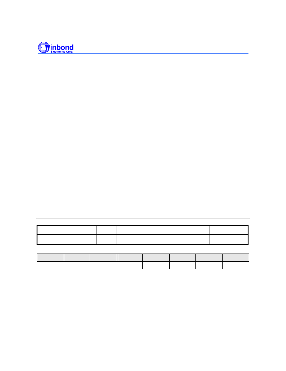
Modem Status Register (MSR)
Register Address R/W
Description
Reset
Value
MSR
0xFFF8.0018
R
MODEM Status Register
0x0000.0000
7
6
5
4
3
2
1
0
DCD# RI# DSR# CTS# DDCD TERI DDSR DCTS
DCD#[7]:
Complement version of Data Carrier Detect (nDCD#) input
RI#[6]:
Complement version of ring indicator (RI#) input
DSR#[5]:
Complement version of data set ready (DSR#) input
CTS#[4]:
Complement version of clear to send (CTS#) input
DDCD [3]:
DCD# State Change
This bit is set whenever DCD# input has changed state, and it will be reset if the CPU reads the MSR.