Rainbow Electronics W90N740 User Manual
Page 159
W90N740
Publication Release Date: November 26, 2004
- 155 -
Revision A4
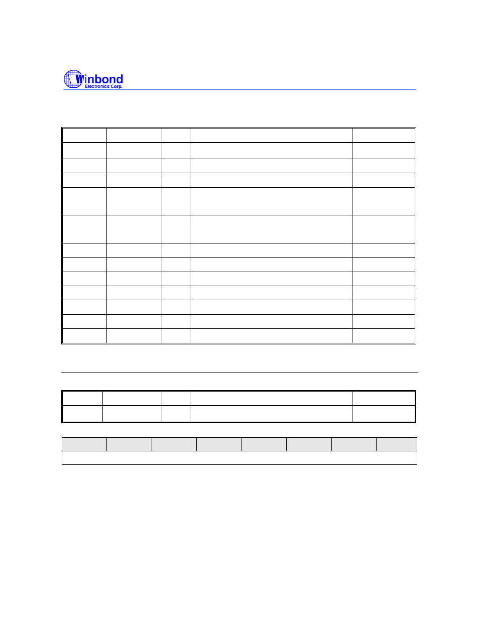
7.9.1 UART Control Registers Map
R: read only, W: write only, R/W: both read and write, C: Only value 0 can be written
REGISTER ADDRESS R/W
DESCRIPTION
RESET
VALUE
RBR
0xFFF8.0000
R
Receive Buffer Register (DLAB = 0)
Undefined
THR
0xFFF8.0000
W
Transmit Holding Register (DLAB = 0)
Undefined
IER
0xFFF8.0004 R/W Interrupt Enable Register (DLAB = 0)
0x0000.0000
DLL
0xFFF8.0000 R/W
Divisor Latch Register (LS)
(DLAB = 1)
0x0000.0000
DLM
0xFFF8.0004 R/W
Divisor Latch Register (MS)
(DLAB = 1)
0x0000.0000
IIR
0xFFF8.0008
R
Interrupt Identification Register
0x8181.8181
FCR
0xFFF8.0008
W
FIFO Control Register
Undefined
LCR
0xFFF8.000C R/W Line Control Register
0x0000.0000
MCR
0xFFF8.0010 R/W Modem Control Register
0x0000.0000
LSR
0xFFF8.0014
R
Line Status Register
0x6060.6060
MSR
0xFFF8.0018
R
MODEM Status Register
0x0000.0000
TOR
0xFFF8.001C R/W Time Out Register
0x0000.0000
Receive Buffer Register (RBR)
Register Address R/W
Description
Reset
Value
RBR
0xFFF8.0000
R
Receive Buffer Register (DLAB = 0)
Undefined
7
6
5
4
3
2
1
0
8-bit Received Data
8-bit Received Data [7:0]
By reading this register, the UART will return an 8-bit data received from SIN pin (LSB first).