Configuration procedure – H3C Technologies H3C SR8800 User Manual
Page 68
52
with Router C and the route information received from Router C. Then, Router A learns the static
route from Router C with the outbound interface being the interface connected to Router B.
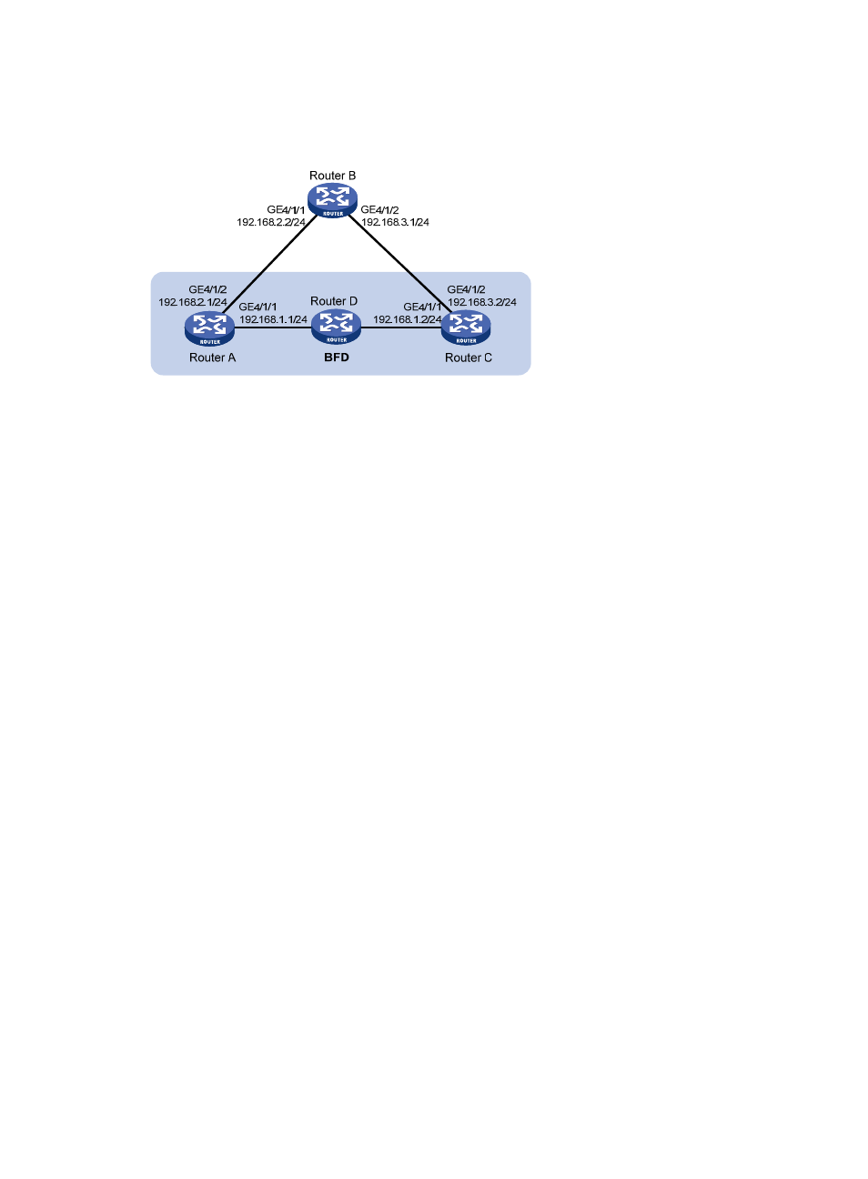
Figure 15 Network diagram
Configuration procedure
1.
Configure RIP basic functions and enable BFD on the interfaces:
# Configure Router A.
[RouterA] rip 1
[RouterA-rip-1] network 192.168.1.0
[RouterA-rip-1] quit
[RouterA] interface GigabitEthernet 4/1/1
[RouterA-GigabitEthernet4/1/1] rip bfd enable
[RouterA-GigabitEthernet4/1/1] quit
[RouterA] rip 2
[RouterA-rip-2] network 192.168.2.0
[RouterA-rip-2] quit
# Configure Router B.
[RouterB] rip 1
[RouterB-rip-1] network 192.168.2.0
[RouterB-rip-1] network 192.168.3.0
[RouterB-rip-1] quit
# Configure Router C.
[RouterC] rip 1
[RouterC-rip-1] network 192.168.1.0
[RouterC-rip-1] network 192.168.3.0
[RouterC-rip-1] import-route static
[RouterC-rip-1] quit
2.
Configure the BFD parameters on GigabitEthernet 4/1/1 of Router A:
[RouterA] bfd session init-mode active
[RouterA] bfd echo-source-ip 11.11.11.11
[RouterA] interface GigabitEthernet 4/1/1
[RouterA-GigabitEthernet4/1/1] bfd min-transmit-interval 500
[RouterA-GigabitEthernet4/1/1] bfd min-receive-interval 500
- H3C SR6600-X H3C SR6600 H3C WX6000 Series Access Controllers H3C WX5000 Series Access Controllers H3C WX3000 Series Unified Switches H3C LSWM1WCM10 Access Controller Module H3C LSWM1WCM20 Access Controller Module H3C LSQM1WCMB0 Access Controller Module H3C LSRM1WCM2A1 Access Controller Module H3C LSBM1WCM2A0 Access Controller Module