Bgp gr configuration example, Network requirements, Configuration procedure – H3C Technologies H3C SR8800 User Manual
Page 274

258
# Define routing policy localpref on Router C to set the local preference of route 1.0.0.0/8 to
200 (the default is 100).
[RouterC] route-policy localpref permit node 10
[RouterC-route-policy] if-match acl 2000
[RouterC-route-policy] apply local-preference 200
[RouterC-route-policy] quit
# Apply the routing policy localpref to the route from the peer 193.1.1.1 on Router C.
[RouterC] bgp 200
[RouterC-bgp] peer 193.1.1.1 route-policy localpref import
[RouterC-bgp] quit
# Display the BGP routing table on Router D.
[RouterD] display bgp routing-table
Total Number of Routes: 2
BGP Local router ID is 194.1.1.1
Status codes: * - valid, ^ - VPNv4 best, > - best, d - damped,
h - history, i - internal, s - suppressed, S - Stale
Origin : i - IGP, e - EGP, ? - incomplete
Network NextHop MED LocPrf PrefVal Path/Ogn
*>i 1.0.0.0 193.1.1.1 0 200 0 100i
* i 192.1.1.1 0 100 0 100i
The route 1.0.0.0/8 learned from Router C is the optimal.
BGP GR configuration example
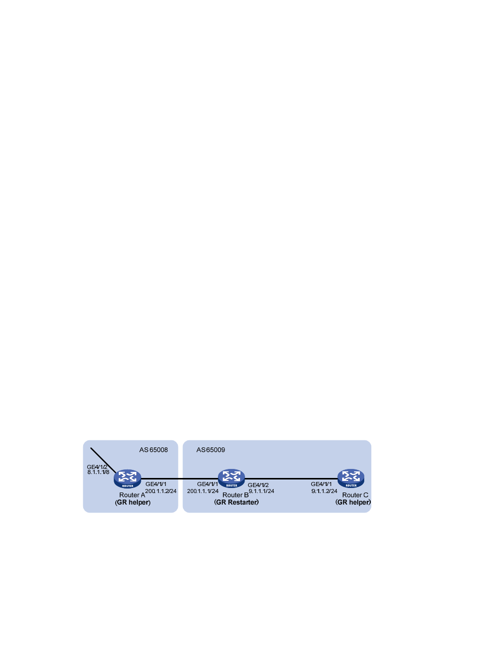
Network requirements
In
are all BGP routers. Between Router A and Router B is an EBGP connection. Router B and
Router C are connected over an IBGP connection. Enable GR capability for BGP so that the
communication between Router A and Router C cannot be affected when an active/standby main board
switchover occurs on Router B.
Figure 97 Network diagram
Configuration procedure
1.
Configure Router A:
# Configure IP addresses for interfaces. (Details not shown)
# Configure the EBGP connection.
- H3C SR6600-X H3C SR6600 H3C WX6000 Series Access Controllers H3C WX5000 Series Access Controllers H3C WX3000 Series Unified Switches H3C LSWM1WCM10 Access Controller Module H3C LSWM1WCM20 Access Controller Module H3C LSQM1WCMB0 Access Controller Module H3C LSRM1WCM2A1 Access Controller Module H3C LSBM1WCM2A0 Access Controller Module
