6pe configuration, Network requirements, Configuration procedure – H3C Technologies H3C SR8800 User Manual
Page 387
371
[RouterD-bgp-af-ipv6] peer 102::1 as-number 200
3.
Configure route reflector:
# Configure Router C as a route reflector, Router B and Router D as its clients.
[RouterC-bgp-af-ipv6] peer 101::2 reflect-client
[RouterC-bgp-af-ipv6] peer 102::2 reflect-client
4.
Verify the configuration:
Use the display bgp ipv6 routing-table command on Router B and Router D respectively, you can
find both of them have learned the network 1::/64.
6PE configuration
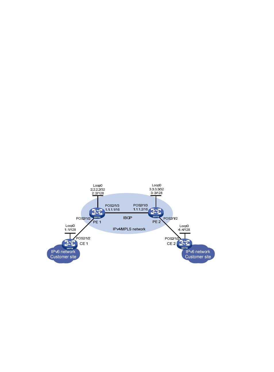
Network requirements
As shown in the following figure:
•
Routers PE 1 and PE 2 support 6PE;
•
Routers CE 1 and CE 2 support IPv6;
•
Between the PE routers is the IPv4/MPLS network of an ISP. The two PEs establish an IPv4 IBGP
connection in between, and the IGP used is OSPF.
•
The CEs reside in IPv6 networks. A CE and a PE use IPv6 link-local addresses to exchange routing
information via a static route;
•
Connect the two IPv6 networks through the IPv4/MPLS network with the 6PE feature.
Figure 120 Network diagram
Configuration procedure
1.
Configure CE 1:
# Enable IPv6 packet forwarding.
[CE1] ipv6
# Specify IP addresses for interfaces.
[CE1] interface Pos 2/1/2
[CE1-Pos2/1/2] ipv6 address auto link-local
[CE1-Pos2/1/2] quit
[CE1] interface loopback0
- H3C SR6600-X H3C SR6600 H3C WX6000 Series Access Controllers H3C WX5000 Series Access Controllers H3C WX3000 Series Unified Switches H3C LSWM1WCM10 Access Controller Module H3C LSWM1WCM20 Access Controller Module H3C LSQM1WCMB0 Access Controller Module H3C LSRM1WCM2A1 Access Controller Module H3C LSBM1WCM2A0 Access Controller Module