Configuring bfd for ospf, Network requirements – H3C Technologies H3C SR8800 User Manual
Page 146
130
Summary Count : 1
Destination: 4.4.4.4/32
Protocol: OSPF Process ID: 1
Preference: 10 Cost: 1
NextHop: 13.13.13.2 Interface: GigabitEthernet3/1/2
BkNextHop: 12.12.12.2 BkInterface: GigabitEthernet3/1/1
RelyNextHop: 0.0.0.0 Neighbor : 0.0.0.0
Tunnel ID: 0x0 Label: NULL
State: Active Adv Age: 00h01m27s
Tag: 0
# Display route 1.1.1.1/32 on Router D. You can find the backup next hop information.
[RouterS] display ip routing-table 1.1.1.1 verbose
Routing Table : Public
Summary Count : 1
Destination: 1.1.1.1/32
Protocol: OSPF Process ID: 1
Preference: 10 Cost: 1
NextHop: 13.13.13.1 Interface: GigabitEthernet3/1/2
BkNextHop: 24.24.24.2 BkInterface: GigabitEthernet3/1/1
RelyNextHop: 0.0.0.0 Neighbor : 0.0.0.0
Tunnel ID: 0x0 Label: NULL
State: Active Adv Age: 00h01m27s
Tag: 0
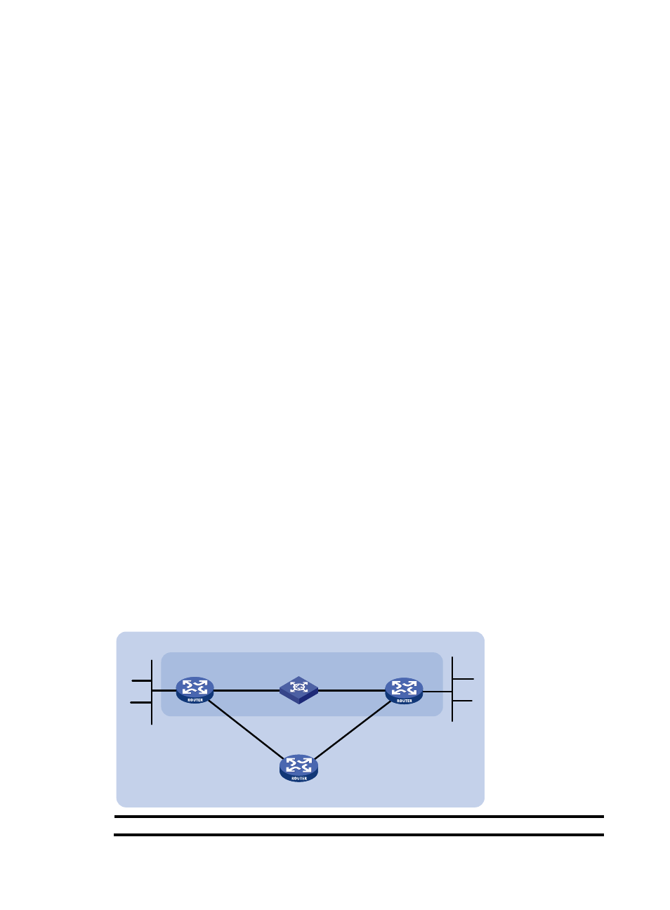
Configuring BFD for OSPF
Network requirements
As shown in
:
•
OSPF is enabled on Router A, Router B and Router C so that they are reachable to each other at the
network layer.
•
After the link over which Router A and Router B communicate through a Layer 2 switch fails, BFD can
quickly detect the failure and notify OSPF of the failure. Router A and Router B then communicate
through Router C.
Figure 48 Network diagram
Device
Interface
IP address
Device
Interface
IP address
GE3/1/1
GE
Router A
Router B
BFD
L 2 Switch
Area 0
Router C
GE
GE
GE
GE
120.1.1.0/ 24
121.1.1.0/ 24
3/1/1
3/1/2
3/1/2
3/1/1
3/1/2
- H3C SR6600-X H3C SR6600 H3C WX6000 Series Access Controllers H3C WX5000 Series Access Controllers H3C WX3000 Series Unified Switches H3C LSWM1WCM10 Access Controller Module H3C LSWM1WCM20 Access Controller Module H3C LSQM1WCMB0 Access Controller Module H3C LSRM1WCM2A1 Access Controller Module H3C LSBM1WCM2A0 Access Controller Module